| |
| |
= 25. CHAPTER 25 — REINFORCEMENT DETAILS | |
| | |
= 25.7 — Transverse reinforcement | |
== 25.7.1 Stirrups | |
=== 25.7.1.1 Stirrups shall extend as close to the compression | |
| and tension surfaces of the member as cover requirements | |
| and proximity of other reinforcement permits and shall be | |
| anchored at both ends. Where used as shear reinforcement, | |
| stirrups shall extend a distance d from extreme compression | |
| fiber. | |
| | |
= R25.7 — Transverse reinforcement | |
| | |
== R25.7.1 Stirrups | |
=== R25.7.1.1 Stirrup legs should be extended as close as practicable | |
| to the compression face of the member because, near | |
| ultimate load, the flexural tension cracks penetrate deeply | |
| toward the compression zone. | |
| It is essential that shear and torsional reinforcement be | |
| adequately anchored at both ends to be fully effective on | |
| either side of any potential inclined crack. This generally | |
| requires a hook or bend at the end of the reinforcement as | |
| provided by this section. | |
| | |
| | |
| American Concrete Institute – Copyrighted © Material – www.concrete.org | |
| 494 ACI 318-19: BUILDING CODE REQUIREMENTS FOR STRUCTURAL CONCRETE | |
| No further reproduction or distribution is permitted. | |
| | |
=== 25.7.1.2 Between anchored ends, each bend in the continuous | |
| portion of a single or multiple U-stirrup and each bend | |
| in a closed stirrup shall enclose a longitudinal bar or strand. | |
| | |
=== 25.7.1.3 Anchorage of deformed bar and wire shall be in | |
| accordance with (a), (b), or (c): | |
| |
| (a) For No. 16 bar and MD200 wire, and smaller, and for | |
| No. 19 through No. 25 bars with fyt ≤ 280 MPa, a standard | |
| hook around longitudinal reinforcement | |
| (b) For No. 19 through No. 25 bars with fyt > 280 MPa, a | |
| standard hook around a longitudinal bar plus an embedment | |
| between midheight of the member and the outside end of | |
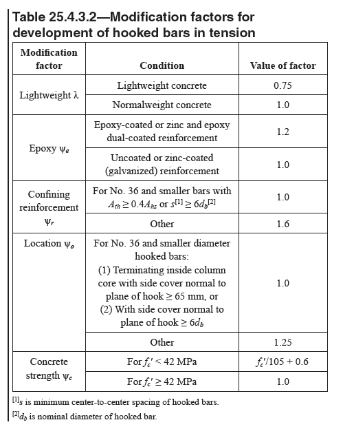
| the hook equal to or greater than 0.17db fyt/(λ sqrt(fc')), with λ | |
| as given in Table 25.4.3.2 | |
| (c) In joist construction, for No. 13 bar and MD130 wire | |
| and smaller, a standard hook | |
| | |
=== R25.7.1.3 Straight deformed bar and wire anchorage is | |
| not permitted because it is difficult to hold such a stirrup in | |
| position during concrete placement. Moreover, the lack of a | |
| standard stirrup hook may make the stirrup ineffective as it | |
| crosses shear cracks near the end of the stirrup. | |
| For a No. 16 or MD200 or smaller stirrup, anchorage is | |
| provided by a standard hook, as defined in 25.3.2, hooked | |
| around a longitudinal bar. | |
| For a No. 19, No. 22, or No. 25 stirrup with fyt of only | |
| 280 MPa, a standard stirrup hook around a longitudinal bar | |
| provides sufficient anchorage. For a No. 19, No. 22, or No. | |
| 25 stirrup with higher strength, the embedment should be | |
| checked. A 135-degree or 180-degree hook is preferred, | |
| but a 90-degree hook may be used provided the free end | |
| of the 90-degree hook is extended the full 12 bar diameters | |
| as required in 25.3.2. Because it is not possible to bend a | |
| No. 19, No. 22, or No. 25 stirrup tightly around a longitudinal | |
| bar and due to the force in a bar with a design stress | |
| greater than 280 MPa, stirrup anchorage depends on both the | |
| type of hook and whatever development length is provided. | |
| A longitudinal bar within a stirrup hook limits the width of | |
| any flexural cracks, even in a tension zone. Because such a | |
| stirrup hook cannot fail by splitting parallel to the plane of | |
| the hooked bar, the hook strength as used in 25.4.3.1(a) has | |
| been adjusted to reflect cover and confinement around the | |
| stirrup hook. | |
| In joists, a small bar or wire can be anchored by a standard | |
| hook not engaging longitudinal reinforcement, allowing a | |
| continuously bent bar to form a series of single-leg stirrups | |
| along the length of the joist. | |
| | |
=== 25.7.1.4 Anchorage of each leg of welded wire reinforcement | |
| forming a single U-stirrup shall be in accordance with | |
| (a) or (b): | |
| |
| (a) Two longitudinal wires spaced at a 50 mm spacing | |
| along the member at the top of the U | |
| (b) One longitudinal wire located not more than d/4 from | |
| the compression face and a second wire closer to the | |
| compression face and spaced not less than 50 mm from | |
| the first wire. The second wire shall be permitted to be | |
| located on the stirrup leg beyond a bend, or on a bend with | |
| an inside diameter of bend of at least 8db. | |
| | |
=== R25.7.1.4 The requirements for anchorage of welded wire | |
| reinforcement stirrups are illustrated in Fig. R25.7.1.4 . | |
| | |
| | |
| American Concrete Institute – Copyrighted © Material – www.concrete.org | |
| PART 8: REINFORCEMENT 495 | |
| 25 Detailing | |
| No further reproduction or distribution is permitted. | |
| | |
| | |
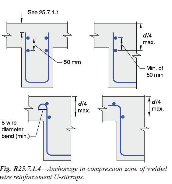
Fig. R25.7.1.4—Anchorage in compression zone of welded | |
| wire reinforcement U-stirrups._ | |
| | |
| | |
=== 25.7.1.5 Anchorage of each end of a single leg stirrup of | |
| welded wire reinforcement shall be with two longitudinal | |
| wires at a minimum spacing of 50 mm in accordance with | |
| (a) and (b): | |
| |
| (a) Inner longitudinal wire at least the greater of d/4 or 50 | |
| mm from d/2; | |
| (b) Outer longitudinal wire at tension face shall not be | |
| farther from the face than the portion of primary flexural | |
| reinforcement closest to the face. | |
| | |
| | |
=== R25.7.1.5 Welded wire reinforcement for shear reinforcement | |
| is commonly used in the precast, prestressed | |
| concrete industry. The rationale for acceptance of straight | |
| sheets of welded wire reinforcement as shear reinforcement | |
| is presented in a report by the Joint PCI/WRI Ad Hoc | |
| Committee on Welded Wire Fabric for Shear Reinforcement | |
| (1980). | |
| The provisions for anchorage of single-leg welded wire | |
| reinforcement in the tension face emphasize the location | |
| of the longitudinal wire at the same depth as the primary | |
| flexural reinforcement to avoid a splitting problem at the | |
| level of the tension reinforcement. Figure R25.7.1.5 illustrates | |
| the anchorage requirements for single-leg welded | |
| wire reinforcement. For anchorage of single-leg welded | |
| wire reinforcement, the Code permits hooks and embedment | |
| length in the compression and tension faces of members | |
| (refer to 25.7.1.3(a) and 25.7.1.4), and embedment only | |
| in the compression face (refer to 25.7.1.3(b)). This section | |
| provides for anchorage of straight, single-leg, welded wire | |
| reinforcement using longitudinal wire anchorage with | |
| adequate embedment length in compression and tension | |
| faces of members. | |
| | |
| | |
| | |
| American Concrete Institute – Copyrighted © Material – www.concrete.org | |
| 496 ACI 318-19: BUILDING CODE REQUIREMENTS FOR STRUCTURAL CONCRETE | |
| No further reproduction or distribution is permitted. | |
| | |
| | |
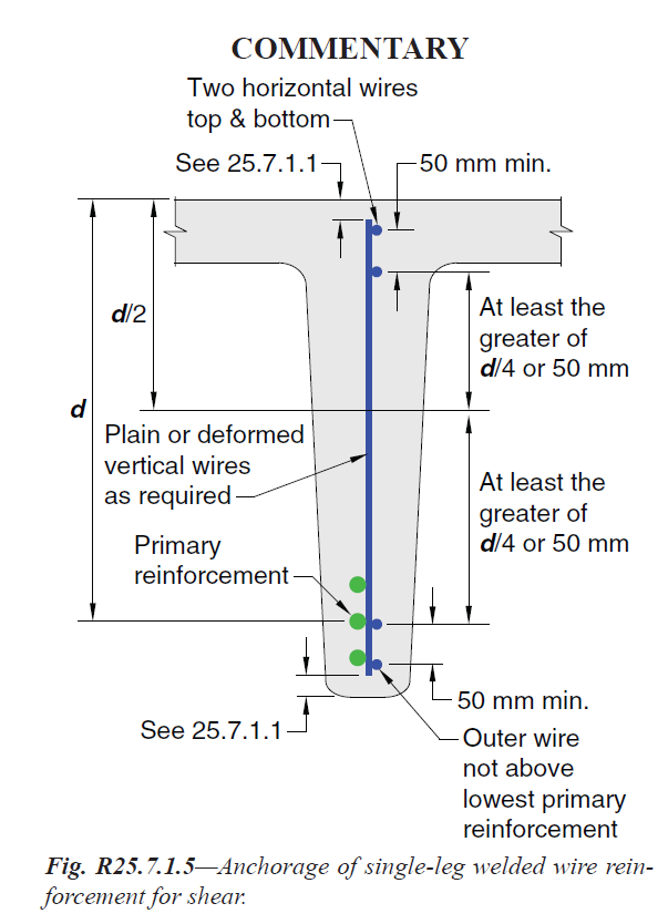
Fig. R25.7.1.5—Anchorage of single-leg welded wire reinforcement | |
| for shear._ | |
| | |
=== 25.7.1.6 Stirrups used for torsion or integrity reinforcement | |
| shall be closed stirrups perpendicular to the axis of the | |
| member. Where welded wire reinforcement is used, transverse | |
| wires shall be perpendicular to the axis of the member. | |
| Such stirrups shall be anchored by (a) or (b): | |
| |
| (a) Ends shall terminate with 135-degree standard hooks | |
| around a longitudinal bar; | |
| (b) In accordance with 25.7.1.3 (a) or (b) or 25.7.1.4, where | |
| the concrete surrounding the anchorage is restrained | |
| against spalling by a flange or slab or similar member. | |
==== 25.7.1.6.1 Stirrups used for torsion or integrity reinforcement | |
| shall be permitted to be made up of two pieces | |
| of reinforcement: a single U-stirrup anchored according to | |
| 25.7.1.6 (a) closed by a crosstie where the 90-degree hook of | |
| the crosstie shall be restrained against spalling by a flange or | |
| slab or similar member. | |
| | |
=== R25.7.1.6 Both longitudinal and closed transverse reinforcement | |
| are required to resist the diagonal tension stresses | |
| due to torsion. The stirrups should be closed because inclined | |
| cracking due to torsion may occur on all faces of a member. | |
| In the case of sections subjected primarily to torsion, the | |
| concrete side cover to the stirrups spalls off at high torsional | |
| moments (Mitchell and Collins 1976). This renders lapspliced | |
| stirrups ineffective, leading to a premature torsional | |
| failure (Behera and Rajagopalan 1969). In such cases, closed | |
| stirrups should not be made up of pairs of U-stirrups lapping | |
| one another. | |
| When a rectangular beam fails in torsion, the corners of | |
| the beam tend to spall off due to the inclined compressive | |
| stresses in the concrete diagonals of the space truss changing | |
| direction at the corner as shown in Fig. R25.7.1.6 (a). In tests | |
| (Mitchell and Collins 1976), closed stirrups anchored by | |
| 90-degree hooks failed when this occurred. For this reason, | |
| 135-degree standard hooks or seismic hooks are preferable | |
| for torsional stirrups in all cases. In regions where | |
| this spalling is prevented by an adjacent slab or flange, | |
| 25.7.1.6 (b) relaxes this requirement and allows 90-degree | |
| hooks because of the added confinement from the slab (refer | |
| to Fig. R25.7.1.6 (b)). | |
| | |
| | |
| | |
| American Concrete Institute – Copyrighted © Material – www.concrete.org | |
| PART 8: REINFORCEMENT 497 | |
| 25 Detailing | |
| No further reproduction or distribution is permitted. | |
| | |
| | |
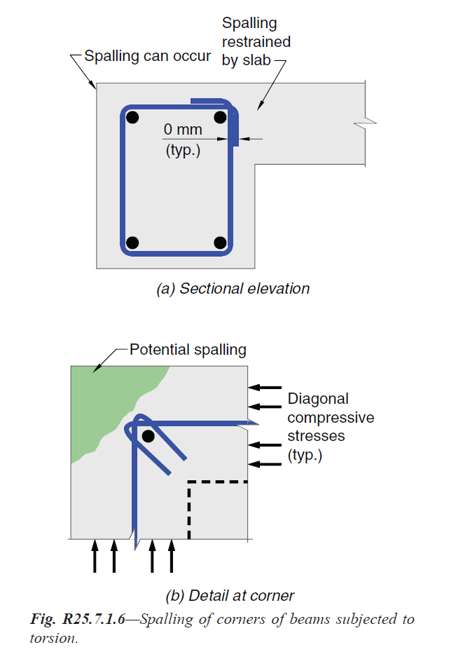
Fig. R25.7.1.6—Spalling of corners of beams subjected to | |
| torsion. | |
| | |
=== 25.7.1.7 Except where used for torsion or integrity reinforcement, | |
| closed stirrups are permitted to be made using | |
| pairs of U-stirrups spliced to form a closed unit where lap | |
| lengths are at least 1.3ℓd. In members with a total depth of at | |
| least 450 mm, such splices with Ab fyt ≤ 40 kN per leg shall | |
| be considered adequate if stirrup legs extend the full available | |
| depth of member. | |
| | |
=== R25.7.1.7 Requirements for lapping of double U-stirrups | |
| to form closed stirrups control over the lap splice provisions | |
| of 25.5.2. Figure R25.7.1.7 illustrates closed stirrup configurations | |
| created with lap splices. | |
| | |
| | |

Fig. R25.7.1.7—Closed stirrup configurations. | |
| | |
| | |
| | |
| | |
| American Concrete Institute – Copyrighted © Material – www.concrete.org | |
| 498 ACI 318-19: BUILDING CODE REQUIREMENTS FOR STRUCTURAL CONCRETE | |
| No further reproduction or distribution is permitted. | |
| | |
| | |
== 25.7.2 Ties | |
=== 25.7.2.1 Ties shall consist of a closed loop of deformed | |
| bar with spacing in accordance with (a) and (b): | |
| |
| (a) Clear spacing of at least (4/3)dagg; | |
| (b) Center-to-center spacing shall not exceed the least | |
| of 16db of longitudinal bar, 48db of tie bar, and smallest | |
| dimension of member. | |
=== 25.7.2.2 Diameter of tie bar shall be at least (a) or (b): | |
| (a) No. 10 enclosing No. 32 or smaller longitudinal bars; | |
| (b) No. 13 enclosing No. 36 or larger longitudinal bars or | |
| bundled longitudinal bars. | |
==== 25.7.2.2.1 As an alternative to deformed bars, deformed | |
| wire or welded wire reinforcement of equivalent area to that | |
| required in 25.7.2.1 shall be permitted subject to the requirements | |
| of Table 20.2.2.4(a). | |
=== 25.7.2.3 Rectilinear ties shall be arranged to satisfy (a) | |
| and (b): | |
| |
| (a) Every corner and alternate longitudinal bar shall have | |
| lateral support provided by the corner of a tie with an | |
| included angle of not more than 135 degrees; | |
| (b) No unsupported bar shall be farther than 150 mm clear | |
| on each side along the tie from a laterally supported bar. | |
| | |
| | |
== R25.7.2 Ties | |
=== R25.7.2.2 These provisions apply to crossties as well as | |
| ties. | |
=== R25.7.2.3 The maximum permissible included angle of | |
| 135 degrees and the exemption of bars located within 150 | |
| mm clear on each side along the tie from adequately tied | |
| bars are illustrated in Fig. R25.7.2.3a . Limited tests (Pfister | |
| 1964 ) on full-size, axially-loaded, tied columns containing | |
| full-length bars (without splices) showed that ties on alternate | |
| longitudinal bars within 150 mm clear of a laterally | |
| supported longitudinal bar are adequate in columns subjected | |
| to axial force. | |
| Continuously wound bars or wires can be considered as | |
| ties, provided their pitch and area are at least equivalent to | |
| the area and spacing of separate ties. Anchorage at the end | |
| of a continuously wound bar or wire should be by a standard | |
| hook as for separate bars or by one additional turn of the tie | |
| pattern (refer to Fig. R25.7.2.3b ). A circular, continuously | |
| wound bar or wire is considered a spiral if it conforms to | |
| 25.7.3; otherwise, it is considered a tie. | |
| | |
| | |
| | |
| American Concrete Institute – Copyrighted © Material – www.concrete.org | |
| PART 8: REINFORCEMENT 499 | |
| 25 Detailing | |
| No further reproduction or distribution is permitted. | |
| | |
| | |
| | |
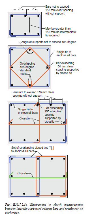
Fig. R25.7.2.3a—Illustrations to clarify measurements | |
| between laterally supported column bars and rectilinear tie | |
| anchorage. | |
| | |
| | |
| American Concrete Institute – Copyrighted © Material – www.concrete.org | |
| 500 ACI 318-19: BUILDING CODE REQUIREMENTS FOR STRUCTURAL CONCRETE | |
| No further reproduction or distribution is permitted. | |
| | |
| | |
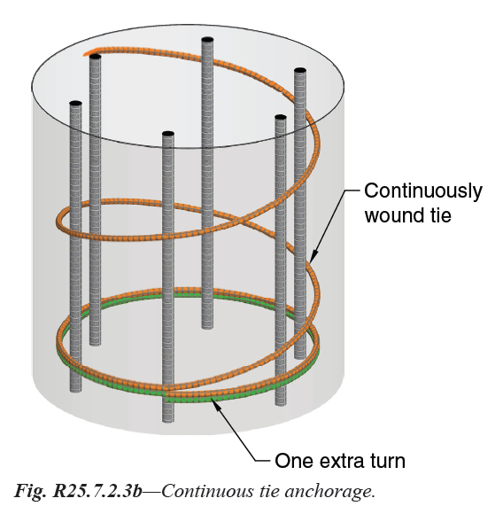
Fig. R25.7.2.3b—Continuous tie anchorage. | |
| | |
==== 25.7.2.3.1 Anchorage of rectilinear ties shall be provided | |
| by standard hooks that conform to 25.3.2 and engage a | |
| longitudinal bar. A tie shall not be made up of interlocking | |
| headed deformed bars. | |
=== 25.7.2.4 Circular ties shall be permitted where longitudinal | |
| bars are located around the perimeter of a circle. | |
==== 25.7.2.4.1 Anchorage of individual circular ties shall be in | |
| accordance with (a) through (c): | |
| |
| (a) Ends shall overlap by at least 150 mm. | |
| (b) Ends shall terminate with standard hooks in accordance | |
| with 25.3.2 that engage a longitudinal bar | |
| (c) Overlaps at ends of adjacent circular ties shall be staggered | |
| around the perimeter enclosing the longitudinal bars | |
| | |
==== R25.7.2.3.1 Standard tie hooks are intended for use with | |
| deformed bars only and should be staggered where possible. | |
=== R25.7.2.4 While the transverse reinforcement in members | |
| with longitudinal bars located around the periphery of a | |
| circle can be either spirals or circular ties, spirals are usually | |
| more effective. | |
==== R25.7.2.4.1 Vertical splitting and loss of tie restraint are | |
| possible where the overlapped ends of adjacent circular ties | |
| are anchored at a single longitudinal bar. Adjacent circular | |
| ties should not engage the same longitudinal bar with end | |
| hook anchorages (refer to Fig. R25.7.2.4.1 ). | |
| | |
| | |
| American Concrete Institute – Copyrighted © Material – www.concrete.org | |
| PART 8: REINFORCEMENT 501 | |
| 25 Detailing | |
| No further reproduction or distribution is permitted. | |
| | |
| | |
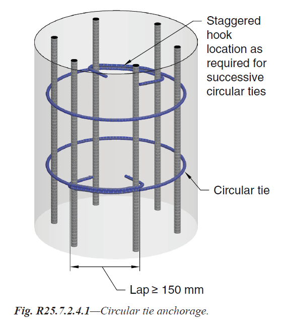
Fig. R25.7.2.4.1—Circular tie anchorage. | |
| | |
| | |
=== 25.7.2.5 Ties to resist torsion shall be perpendicular to the | |
| axis of the member anchored by either (a) or (b): | |
| (a) Ends shall terminate with 135-degree standard hooks | |
| or seismic hooks around a longitudinal bar; | |
| (b) In accordance with 25.7.1.3(a) or (b) or 25.7.1.4, where | |
| the concrete surrounding the anchorage is restrained | |
| against spalling. | |
| | |
| R25.7.2.5 Refer to R25.7.1.6. | |
| | |
== 25.7.3 Spirals | |
=== 25.7.3.1 Spirals shall consist of evenly spaced continuous | |
| bar or wire with clear spacing conforming to (a) and (b): | |
| |
| (a) At least the greater of 25 mm and (4/3)dagg | |
| (b) Not greater than 75 mm | |
=== 25.7.3.2 For cast-in-place construction, spiral bar or wire | |
| diameter shall be at least 9.5 mm. | |
=== 25.7.3.3 Except for transverse reinforcement in deep foundations, | |
| the volumetric spiral reinforcement ratio ρs shall | |
| satisfy Eq. (25.7.3.3). | |
| |
| ρs >= 0.45 (Ag/Ach-1)(fc'/fyt) | |
| |
| (25.7.3.3) | |
| where the value of fyt shall not be taken greater than | |
| 690 MPa. | |
| | |
== R25.7.3 Spirals | |
=== R25.7.3.1 Spirals should be held firmly in place, at proper | |
| pitch and alignment, to prevent displacement during concrete | |
| placement. | |
=== R25.7.3.2 For practical considerations in cast-in-place | |
| construction, the minimum diameter of spiral reinforcement | |
| is 9.5 mm (No. 10 deformed or plain bar, or MD70 deformed | |
| or MW70 plain wire). | |
| Standard spiral sizes are 9.5, 12.7, and 16 mm diameter | |
| for hot-rolled or cold-drawn material, plain or deformed. | |
=== R25.7.3.3 The effect of spiral reinforcement in increasing | |
| the strength of the concrete within the core is not fully realized | |
| until the column has been subjected to a load and deformation | |
| sufficient to cause the concrete shell outside the core | |
| to spall off. The amount of spiral reinforcement required by | |
| Eq. (25.7.3.3) is intended to provide additional strength for | |
| concentrically loaded columns equal to or slightly greater | |
| than the strength lost when the shell spalls off. The deriva- | |
| | |
| American Concrete Institute – Copyrighted © Material – www.concrete.org | |
| 502 ACI 318-19: BUILDING CODE REQUIREMENTS FOR STRUCTURAL CONCRETE | |
| No further reproduction or distribution is permitted. | |
| | |
=== R25.7.3.3 Continuation | |
| tion of Eq. (25.7.3.3) is given by Richart (1933). Tests and | |
| experience show that columns containing the amount of | |
| spiral reinforcement required by this section exhibit considerable | |
| toughness and ductility. Research (Richart et al. 1929; | |
| Richart 1933; Pessiki et al. 2001; Saatcioglu and Razvi | |
| 2002) has also indicated that up to 690 MPa yield strength | |
| reinforcement can be effectively used for confinement. | |
| | |
| | |
=== 25.7.3.4 Spirals shall be anchored by 1-1/2 extra turns of | |
| spiral bar or wire at each end. | |
| | |
=== R25.7.3.4 Spiral anchorage is illustrated in | |
| Fig. R25.7.3.4 . | |
| | |
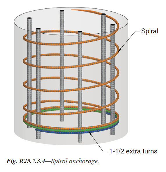
Fig. R25.7.3.4—Spiral anchorage. | |
| | |
=== 25.7.3.5 Spirals are permitted to be spliced by (a) or (b): | |
| (a) Mechanical or welded splices in accordance with | |
| 25.5.7 | |
| (b) Lap splices in accordance with 25.7.3.6 for fyt not | |
| exceeding 420 MPa; | |
=== 25.7.3.6 Spiral lap splices shall be at least the greater of | |
| 300 mm and the lap length in Table 25.7.3.6 . | |
| | |
| American Concrete Institute – Copyrighted © Material – www.concrete.org | |
| PART 8: REINFORCEMENT 503 | |
| 25 Detailing | |
| No further reproduction or distribution is permitted. | |
| | |

Table 25.7.3.6—Lap length for spiral reinforcement | |
| | |
| | |
| | |
== 25.7.4 Hoops | |
=== 25.7.4.1 Hoops shall consist of a closed tie or continuously | |
| wound tie, which can consist of several reinforcement | |
| elements each having seismic hooks at both ends. | |
| | |
== R25.7.4 Hoops | |
| R25.7.4.1 Refer to R25.7.2.4. | |
| | |
=== 25.7.4.2 The ends of the reinforcement elements in hoops | |
| shall be anchored using seismic hooks that conform to 25.3.4 | |
| and engage a longitudinal bar. A hoop shall not be made up | |
| of interlocking headed deformed bars. | |
| | |
| American Concrete Institute – Copyrighted © Material – www.concrete.org | |
| 504 ACI 318-19: BUILDING CODE REQUIREMENTS FOR STRUCTURAL CONCRETE | |
| No further reproduction or distribution is permitted. | |
| | |
[ Lanjut Ke 25.8—Post-tensioning anchorages and couplers ... ] | |
| |
| |
| |