| |
| |
= 18.14 — Members not designated as part of the | |
| seismic-force-resisting system_ | |
== 18.14.1 Scope | |
=== 18.14.1.1 This section shall apply to members not designated | |
| as part of the seismic-force-resisting system in structures | |
| assigned to SDC D, E, and F. | |
== 18.14.2 Design actions | |
=== 18.14.2.1 Members not designated as part of the seismic-force- | |
| resisting system shall be evaluated for gravity load | |
| combinations of 5.3 including the effect of vertical ground | |
| motion acting simultaneously with the design displacement δu. | |
| | |
| | |
= R18.14 — Members not designated as part of the | |
| seismic-force-resisting system_ | |
| This section applies only to structures assigned to SDC | |
| D, E, or F. For those SDCs, all structural members not | |
| designated as a part of the seismic-force-resisting system | |
| are required to be designed to support gravity loads and the | |
| load effects of vertical ground motion, while subjected to the | |
| design displacement. For concrete structures, the provisions | |
| of this section satisfy this requirement for columns, beams, | |
| slabs, and wall piers of the gravity system. | |
| Design displacement is defined in Chapter 2. Models | |
| used to determine design displacement of buildings should | |
| be chosen to produce results that conservatively bound the | |
| values expected during the design earthquake and should | |
| include, as appropriate, effects of concrete cracking, foundation | |
| flexibility, and deformation of floor and roof diaphragms. | |
| The provisions of 18.14 are intended to enable ductile | |
| flexural yielding of columns, beams, slabs, and wall piers | |
| under the design displacement, by providing sufficient | |
| confinement and shear strength in elements that yield. | |
| | |
| | |
== 18.14.3 Cast-in-place beams, columns, and joints | |
=== 18.14.3.1 Cast-in-place beams, columns, and joints | |
| shall be detailed in accordance with 18.14.3.2 or 18.14.3.3 | |
| depending on the magnitude of moments and shears induced | |
| in those members when subjected to the design displacement | |
| δu. If effects of δu are not explicitly checked, the provisions | |
| of 18.14.3.3 shall be satisfied. | |
| | |
== R18.14.3 Cast-in-place beams, columns, and joints | |
=== R18.14.3.1 Cast-in-place columns and beams are assumed | |
| to yield if the combined effects of factored gravity loads and | |
| design displacements exceed the strengths specified, or if the | |
| effects of design displacements are not calculated. Requirements | |
| for transverse reinforcement and shear strength vary | |
| with member type and whether the member yields under the | |
| design displacement. | |
| | |
=== 18.14.3.2 Where the induced moments and shears do not | |
| exceed the design moment and shear strength of the frame | |
| member, (a) through (d) shall be satisfied: | |
| |
| (a) Beams shall satisfy 18.6.3.1. Transverse reinforcement | |
| shall be provided throughout the length of the beam | |
| at spacing not to exceed d/2. Where factored axial force | |
| exceeds Ag fc′/10, transverse reinforcement shall be hoops | |
| satisfying 18.7.5.2 at a spacing not to exceed the lesser of | |
| 6db of the smallest enclosed longitudinal bar and 150 mm. | |
| (b) Columns shall satisfy 18.7.4.1 and 18.7.6. Spiral reinforcement | |
| satisfying 25.7.3 or hoop reinforcement satisfying | |
| 25.7.4 shall be provided over the full length of the | |
| column with spacing not to exceed the lesser of 6db of | |
| the smallest enclosed longitudinal bar and 150 mm Transverse | |
| reinforcement satisfying 18.7.5.2(a) through (e) | |
| shall be provided over a length ℓo, as defined in 18.7.5.1, | |
| from each joint face. | |
| (c) Columns with factored gravity axial forces exceeding | |
| 0.35Po shall satisfy 18.14.3.2(b) and 18.7.5.7. The minimum | |
| amount of transverse reinforcement provided shall be, for | |
| rectilinear hoops, one-half the greater of Table 18.7.5.4 | |
| parts (a) and (b) and, for spiral or circular hoops, one-half | |
| the greater of Table 18.7.5.4 parts (d) and (e). This transverse | |
=== 18.14.3.2 Continuation | |
| reinforcement shall be provided over a length ℓo, as defined | |
| in 18.7.5.1, from each joint face. | |
| (d) Joints shall satisfy Chapter 15. | |
=== 18.14.3.3 Where the induced moments or shears exceed | |
| ϕMn or ϕVn of the frame member, or if induced moments or | |
| shears are not calculated, (a) through (d) shall be satisfied: | |
| (a) Materials, mechanical splices, and welded splices shall | |
| satisfy the requirements for special moment frames in | |
| 18.2.5 through 18.2.8. | |
| (b) Beams shall satisfy 18.14.3.2(a) and 18.6.5. | |
| (c) Columns shall satisfy 18.7.4, 18.7.5, and 18.7.6. | |
| (d) Joints shall satisfy 18.4.4.1. | |
| | |
| | |
| American Concrete Institute – Copyrighted © Material – www.concrete.org | |
| PART 5: EARTHQUAKE RESISTANCE 351 | |
| 18 Seismic | |
| No further reproduction or distribution is permitted. | |
| | |
== 18.14.4 Precast beams and columns | |
=== 18.14.4.1 Precast concrete frame members assumed not to | |
| contribute to lateral resistance, including their connections, | |
| shall satisfy (a) through (d): | |
| (a) Requirements of 18.14.3 | |
| (b) Ties specified in 18.14.3.2(b) over the entire column | |
| height, including the depth of the beams | |
| (c) Structural integrity reinforcement, in accordance with | |
| 4.10 | |
| (d) Bearing length at the support of a beam shall be at least | |
| 50 mm longer than determined from 16.2.6 | |
| | |
== R18.14.4 Precast beams and columns | |
=== R18.14.4.1 Damage to some buildings with precast | |
| concrete gravity systems during the 1994 Northridge earthquake | |
| was attributed to several factors addressed in this | |
| section. Columns should contain ties over their entire height, | |
| frame members not proportioned to resist earthquake forces | |
| should be tied together, and longer bearing lengths should | |
| be used to maintain integrity of the gravity system during | |
| ground motion. The 50 mm increase in bearing length is | |
| based on an assumed 4 percent story drift ratio and 1.3 m | |
| beam depth, and is considered to be conservative for the | |
| ground motions expected for structures assigned to SDC D, | |
| E, or F. In addition to this provision, precast frame members | |
| assumed not to contribute to lateral resistance should also | |
| satisfy the requirements for cast-in-place construction | |
| addressed in 18.14.3, as applicable. | |
| | |
== 18.14.5 Slab-column connections | |
=== 18.14.5.1 For slab-column connections of two-way slabs | |
| without beams, slab shear reinforcement satisfying the | |
| requirements of 18.14.5.3 and either 8.7.6 or 8.7.7 shall be | |
| provided at any slab critical section defined in 22.6.4.1 for | |
| the following conditions: | |
| (a) Nonprestressed slabs where Δx/hsx ≥ 0.035 – 0.05vuv/(ϕvc) | |
| (b) Unbonded post-tensioned slabs with fpc in each direction | |
| meeting the requirements of 8.6.2.1, where Δx/hsx ≥ | |
| 0.040 – 0.05vuv/(ϕvc) | |
| The load combinations to be evaluated for vuv shall only | |
| include those with E. The value of (Δx/hsx) shall be taken as | |
| the greater of the values of the adjacent stories above and below | |
| the slab-column connection, vc shall be calculated in accordance | |
| with 22.6.5; and, for unbonded post-tensioned slabs, the | |
| value of Vp shall be taken as zero when calculating vc. | |
| | |
== R18.14.5 Slab-column connections | |
=== R18.14.5.1 Provisions for shear reinforcement at slabcolumn | |
| connections are intended to reduce the likelihood | |
| of slab punching shear failure if the design story drift ratio | |
| exceeds the value specified. | |
| No calculation of induced moments is required, based on | |
| research (Megally and Ghali 2002; Moehle 1996; Kang and | |
| Wallace 2006; Kang et al. 2007) that identifies the likelihood | |
| of punching shear failure considering the story drift | |
| ratio and shear stress vuv due to gravity loads and the vertical | |
| component of earthquake loads, without moment transfer, | |
| about the slab critical section. Figure R18.14.5.1 illustrates | |
| the requirement for nonprestressed and unbonded posttensioned | |
| slab-column connections. The requirement can be | |
| satisfied by adding slab shear reinforcement, increasing slab | |
| thickness, changing the design to reduce the design story | |
| drift ratio, or a combination of these. | |
| If column capitals, drop panels, shear caps, or other | |
| changes in slab thickness are used, the requirements of | |
| 18.14.5 are evaluated at all potential critical sections, as | |
| required by 22.6.5.1. | |
=== R18.14.5.1 Continuation | |
| Post-tensioned slab-column connections with fpc in each | |
| direction not meeting the requirements of 8.6.2.1 can be | |
| designed as nonprestressed slab-column connections in | |
| accordance with 8.2.3._ | |
| | |
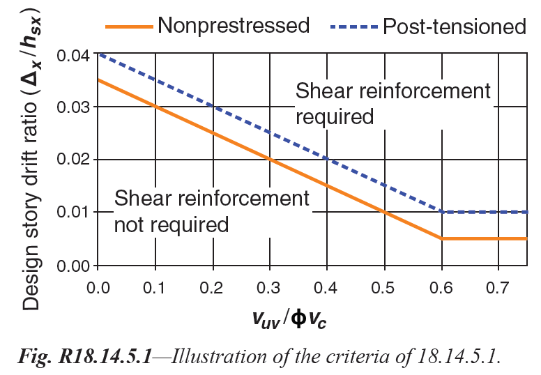
Fig. R18.14.5.1—Illustration of the criteria of 18.14.5.1. | |
| | |
| American Concrete Institute – Copyrighted © Material – www.concrete.org | |
| 352 ACI 318-19: BUILDING CODE REQUIREMENTS FOR STRUCTURAL CONCRETE | |
| No further reproduction or distribution is permitted. | |
| | |
| | |
=== 18.14.5.2 The shear reinforcement requirements of | |
| 18.14.5.1 need not be satisfied if (a) or (b) is met: | |
| (a) Δx/hsx ≤ 0.005 for nonprestressed slabs | |
| (b) Δx/hsx ≤ 0.01 for unbonded post-tensioned slabs with | |
| fpc in each direction meeting the requirements of 8.6.2.1 | |
=== 18.14.5.3 Required slab shear reinforcement shall provide | |
| vs ≥ 0.29 sqrt(fc') at the slab critical section and shall extend | |
| at least four times the slab thickness from the face of the | |
| support adjacent to the slab critical section. | |
| | |
| | |
== 18.14.6 Wall piers | |
=== 18.14.6.1 Wall piers not designated as part of the seismicforce- | |
| resisting system shall satisfy the requirements of | |
=== 18.10.8. Where the general building code includes provisions | |
| to account for overstrength of the seismic-forceresisting | |
| system, it shall be permitted to calculate the design | |
| shear force as Ωo times the shear induced under design | |
| displacements, δu. | |
| | |
| | |
== R18.14.6 Wall piers | |
=== R18.14.6.1 Section 18.10.8 requires that the design shear | |
| force be determined according to 18.7.6.1, which in some | |
| cases may result in unrealistically large forces. As an alternative, | |
| the design shear force can be determined as the product | |
| of an overstrength factor and the shear induced when the | |
| wall pier is displaced by δu. The overstrength factor Ωo | |
| included in FEMA P749, ASCE/SEI 7, and the 2018 IBC | |
| can be used for this purpose. | |
| | |
| | |
| American Concrete Institute – Copyrighted © Material – www.concrete.org | |
| PART 5: EARTHQUAKE RESISTANCE 353 | |
| 18 Seismic | |
| No further reproduction or distribution is permitted. | |
| | |
| | |
| 354 ACI 318-19: BUILDING CODE REQUIREMENTS FOR STRUCTURAL CONCRETE | |
| American Concrete Institute – Copyrighted © Material – www.concrete.org | |
| No further reproduction or distribution is permitted. | |
| | |
[ Lanjut Ke 19—CONCRETE: DESIGN AND DURABILITY REQUIREMENTS ... ] | |
| |
| |
| |