| |
| |
= 18.13 — Foundations | |
| | |
== 18.13.1 Scope | |
=== 18.13.1.1 This section shall apply to foundations resisting | |
| earthquake-induced forces or transferring earthquake induced | |
| forces between structure and ground. | |
=== 18.13.1.2 The provisions in this section for piles, drilled | |
| piers, caissons, and slabs-on-ground shall supplement other | |
| applicable Code design and construction criteria, including | |
| 1.4.6 and 1.4.7. | |
== 18.13.2 Footings, foundation mats, and pile caps | |
=== 18.13.2.1 The provisions of this section shall apply to | |
| structures assigned to SDC D, E, or F. | |
=== 18.13.2.2 Longitudinal reinforcement of columns and | |
| structural walls resisting forces induced by earthquake | |
| effects shall extend into the footing, mat, or pile cap, and | |
| shall be fully developed for tension at the interface. | |
=== 18.13.2.3 Columns designed assuming fixed-end conditions | |
| at the foundation shall comply with 18.13.2.2 and, | |
| if hooks are required, longitudinal reinforcement resisting | |
| flexure shall have 90-degree hooks near the bottom of the | |
| foundation with the free end of the bars oriented toward the | |
| center of the column. | |
| | |
| | |
= R18.13 — Foundations | |
== R18.13.1 Scope | |
| Requirements for foundations supporting buildings | |
| assigned to SDC C, D, E, or F represent a consensus of a | |
| minimum level of good practice in designing and detailing | |
| concrete foundations. However, because repairs to foundations | |
| can be extremely difficult and expensive, it may be | |
| desirable that the elements of the foundation remain essentially | |
| elastic during strong ground motions. Methods to | |
| achieve this goal include designing the foundation to include | |
| an overstrength factor or an increased seismic demand level | |
| when compared to the superstructure, or comparing strengths | |
| to demands predicted by nonlinear response history analyses | |
| with appropriate consideration of uncertainty in demands | |
| (Klemencic et al. 2012). | |
== R18.13.2 Footings, foundation mats, and pile caps | |
=== R18.13.2.3 Tests (Nilsson and Losberg 1976) have | |
| demonstrated that flexural members terminating in a footing, | |
| slab, or beam (a T-joint or L-joint) should have their hooks | |
| turned inward toward the axis of the member for the joint to | |
| be able to resist the flexure in the member forming the stem | |
| of the T or L. | |
| | |
| | |
| American Concrete Institute – Copyrighted © Material – www.concrete.org | |
| PART 5: EARTHQUAKE RESISTANCE 343 | |
| 18 Seismic | |
| No further reproduction or distribution is permitted. | |
| | |
| | |
=== 18.13.2.4 Columns or boundary elements of special structural | |
| walls that have an edge within one-half the footing | |
| depth from an edge of the footing shall have transverse | |
| reinforcement in accordance with 18.7.5.2 through 18.7.5.4 | |
| provided below the top of the footing. This reinforcement | |
| shall extend into the footing, mat, or pile cap a length equal | |
| to the development length, calculated for fy in tension, of | |
| the column or boundary element longitudinal reinforcement. | |
=== 18.13.2.5 Where earthquake effects create uplift forces in | |
| boundary elements of special structural walls or columns, | |
| flexural reinforcement shall be provided in the top of the | |
| footing, mat, or pile cap to resist actions resulting from the | |
| factored load combinations, and shall be at least that required | |
| by 7.6.1 or 9.6.1. | |
=== 18.13.2.6 Structural plain concrete in footings and basement | |
| walls shall be in accordance with 14.1.4. | |
=== 18.13.2.7 Pile caps incorporating batter piles shall be | |
| designed to resist the full compressive strength of the batter | |
| piles acting as short columns. The slenderness effects of | |
| batter piles shall be considered for the portion of the piles | |
| in soil that is not capable of providing lateral support, or in | |
| air or water. | |
| | |
=== R18.13.2.4 Columns or boundary members supported | |
| close to the edge of the foundation, as often occurs near | |
| property lines, should be detailed to prevent an edge failure | |
| of the footing, pile cap, or mat. | |
=== R18.13.2.5 The purpose of this section is to emphasize | |
| that top reinforcement in footings, mats, and pile caps may | |
| be required, in addition to other required reinforcement. | |
=== R18.13.2.6 Foundation and basement walls should be | |
| reinforced in buildings assigned to SDC D, E, or F. | |
=== R18.13.2.7 Batter piles typically attract higher lateral | |
| forces during earthquakes than vertical piles. Extensive | |
| structural damage has been observed at the junction of batter | |
| piles and building foundations. The pile cap and surrounding | |
| structure should be designed for the potentially large forces | |
| that can be developed in batter piles. | |
| | |
== 18.13.3 Grade beams and slabs-on-ground | |
=== 18.13.3.1 For structures assigned to SDC D, E, or F, grade | |
| beams and beams that are part of a mat foundation subjected | |
| to flexure from columns that are part of the seismic-forceresisting | |
| system shall be in accordance with 18.6. | |
=== 18.13.3.2 For structures assigned to SDC C, D, E, or F, | |
| slabs-on-ground that resist in-plane earthquake forces from | |
| walls or columns that are part of the seismic-force-resisting | |
| system shall be designed as diaphragms in accordance with | |
| 18.12. The construction documents shall clearly indicate that | |
| the slab-on-ground is a structural diaphragm and part of the | |
| seismic-force-resisting system. | |
| | |
== R18.13.3 Grade beams and slabs-on-ground | |
| For earthquake conditions, slabs-on-ground (soil-supported | |
| slabs) are often part of the lateral-force-resisting system and | |
| should be designed in accordance with this Code as well as | |
| other appropriate standards or guidelines (refer to 1.4.8). | |
=== R18.13.3.1 Grade beams resisting flexural stresses from | |
| column moments should have reinforcement details similar | |
| to the beams of the frame above the foundation. | |
=== R18.13.3.2 Slabs-on-ground often act as a diaphragm to | |
| tie the building together at the ground level and minimize the | |
| effects of out-of-phase ground motion that may occur over | |
| the footprint of the building. The construction documents | |
| should clearly state that these slabs-on-ground are structural | |
| members so as to prohibit saw cutting of the slab. | |
| | |
== 18.13.4 Foundation seismic ties | |
=== 18.13.4.1 For structures assigned to SDC C, D, E, or F, | |
| individual pile caps, piers, or caissons shall be interconnected | |
| by foundation seismic ties in orthogonal directions, | |
| unless it can be demonstrated that equivalent restraint is | |
| provided by other means. | |
| | |
== R18.13.4 Foundation seismic ties | |
=== R18.13.4.1 The foundation seismic ties should sufficiently | |
| interconnect foundations to act as a unit and be designed to | |
| minimize the relative movement of an individual column or | |
| tie relative to the foundation. This is essential where surface | |
| soils are soft enough to require deep foundations or where | |
| the site soils are susceptible to liquefaction. | |
| | |
| | |
| American Concrete Institute – Copyrighted © Material – www.concrete.org | |
| 344 ACI 318-19: BUILDING CODE REQUIREMENTS FOR STRUCTURAL CONCRETE | |
| No further reproduction or distribution is permitted. | |
| | |
=== 18.13.4.2 For structures assigned to SDC D, E, or F, individual | |
| spread footings founded on soil defined in ASCE/SEI | |
| 7 as Site Class E or F shall be interconnected by foundation | |
| seismic ties. | |
=== 18.13.4.3 Where required, foundation seismic ties shall | |
| have a design strength in tension and compression at least | |
| equal to 0.1SDS times the greater of the pile cap or column | |
| factored dead load plus factored live load unless it is demonstrated | |
| that equivalent restraint will be provided by (a), (b), | |
| (c), or (d): | |
| (a) Reinforced concrete beams within the slab-on-ground | |
| (b) Reinforced concrete slabs-on-ground | |
| (c) Confinement by competent rock, hard cohesive soils, | |
| (d) Other means approved by the building official | |
=== 18.13.4.4 For structures assigned to SDC D, E, or F, grade | |
| beams designed to act as horizontal foundation seismic ties | |
| between pile caps or footings shall have continuous longitudinal | |
| reinforcement that shall be developed within or beyond | |
| the supported column or anchored within the pile cap or | |
| footing at all discontinuities and shall satisfy (a) and (b): | |
| (a) The smallest cross-sectional dimension of the grade | |
| beam shall be at least equal to the clear spacing between | |
| connected columns divided by 20, but need not exceed | |
| (b) Closed tie transverse reinforcement shall be provided at | |
| a spacing not to exceed the lesser of 0.5 times the smallest | |
| orthogonal cross-sectional dimension and 300 mm. | |
| | |
=== R18.13.4.2 The ties between footings should have the same | |
| characteristics as the ties between pile caps in R18.13.4.1. | |
=== R18.13.4.3 The minimum foundation seismic tie design | |
| strength requirement based on a percentage of the factored | |
| dead plus live load provides a minimum connection between | |
| foundation elements. Other types of restraint can be used | |
| if substantiated as equivalent to the minimum tie design | |
| strength. The required design strength for the tie beam must | |
| be at least equal to 0.1SDS times the larger force on either end | |
| of the tie beam, and that force is from the column or pile cap, | |
| whichever applies. | |
| | |
== 18.13.5 Deep foundations | |
=== 18.13.5.1 This section shall apply to the following types | |
| (a) Uncased cast-in-place concrete drilled or augered piles | |
| (b) Metal cased concrete piles | |
| (c) Concrete filled pipe piles | |
| (d) Precast concrete piles | |
=== 18.13.5.2 For structures assigned to SDC C, D, E, or F, | |
| piles, piers, or caissons resisting tension loads shall have | |
| continuous longitudinal reinforcement over their length to | |
| resist design tension forces. | |
=== 18.13.5.3 For structures assigned to SDC C, D, E, or F, the | |
| minimum longitudinal and transverse reinforcement required | |
| by 18.13.5.7 through 18.13.5.10 shall be extended over the | |
| entire unsupported length for the portion of deep foundation | |
| member in air or water, or in soil that is not capable | |
| of providing adequate lateral restraint to prevent buckling | |
| throughout this length. | |
| | |
| | |
== R18.13.5 Deep foundations | |
| Adequate performance of piles and caissons for earthquake | |
| effects requires that these provisions be met in addition | |
| to other applicable standards or guidelines (refer to | |
| R1.4.7). | |
=== R18.13.5.3 Minimum reinforcement lengths for both | |
| longitudinal and transverse reinforcement are based on | |
| the assumption that soil is capable of providing lateral | |
| support. For portions of the pile above ground, typically in | |
| air or water, or where soil is not capable of providing this | |
| lateral restraint, the minimum reinforced lengths should be | |
| increased, and the member should be designed as a column. | |
| | |
| | |
| American Concrete Institute – Copyrighted © Material – www.concrete.org | |
| PART 5: EARTHQUAKE RESISTANCE 345 | |
| 18 Seismic | |
| No further reproduction or distribution is permitted. | |
| | |
| | |
=== 18.13.5.4 For structures assigned to SDC C, D, E, or F, | |
| hoops, spirals, and ties in deep foundation members shall be | |
| terminated with seismic hooks. | |
=== 18.13.5.5 For structures assigned to SDC D, E, or F or | |
| located in Site Class E or F, concrete deep foundation | |
| members shall have transverse reinforcement in accordance | |
| with 18.7.5.2, 18.7.5.3, and Table 18.7.5.4 Item (e) within | |
| seven member diameters above and below the interfaces | |
| between strata that are hard or stiff and strata that are liquefiable | |
| or soft. | |
=== 18.13.5.6 For structures assigned to SDC D, E, or F, in | |
| foundations supporting one- and two-story stud bearing wall | |
| construction, concrete piles, piers or caissons, and foundation | |
| ties are exempt from the transverse reinforcement | |
| requirements of 18.13.5.3 through 18.13.5.5. | |
| | |
| | |
=== R18.13.5.5 During earthquakes, piles can be subjected to | |
| high flexural and shear demands at points of discontinuity, | |
| such as at interfaces between stiff and soft soil strata. ASCE/ | |
| SEI 7 defines limits for soil strata. Transverse reinforcement | |
| is required in these regions to provide ductile behavior. | |
| In determining the portions of a pile with increased transverse | |
| reinforcement, accommodations are often made to the | |
| length of the reinforced zone for transverse reinforcement to | |
| account for variations in the driven pile tip elevations and | |
| variations in the interface elevations between stiff and soft | |
| soil strata. | |
| | |
=== 18.13.5.7 Uncased cast-in-place drilled or augered | |
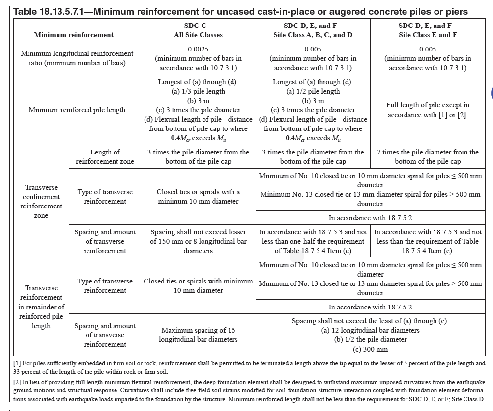
==== 18.13.5.7.1 For structures assigned to SDC C, D, E, or | |
| F, reinforcement shall be provided in uncased cast-in-place | |
| drilled or augered concrete piles where required by analysis | |
| and in accordance with the requirements in Table 18.13.5.7.1. | |
| | |
| | |
=== R18.13.5.7 Uncased cast-in-place drilled or augered | |
==== R18.13.5.7.1 Longitudinal and transverse reinforcement | |
| requirements prescribed by this section result in ductility | |
| consistent with the applicable Seismic Design Category | |
| (SDC) to withstand ground deformation that occurs during | |
| earthquakes. | |
| Where piles are subjected to significant uplift forces, the | |
| longitudinal reinforcement length required by analysis may | |
| exceed the minimum reinforcement length requirements. | |
| Transverse reinforcement is required at the top of the pile | |
| to provide ductile performance where flexural yielding can | |
| potentially occur. For SDC D, E, and F and Site Classes A, | |
| B, C, and D, one-half of the transverse reinforcement for | |
| special moment frame columns is acceptable because some | |
| level of confinement is attributed to competent soils. For Site | |
| Class E and F, full column confinement is required because | |
| the soils are either liquefiable or not considered competent | |
| enough to provide confinement. | |
| | |
| | |
| American Concrete Institute – Copyrighted © Material – www.concrete.org | |
| 346 ACI 318-19: BUILDING CODE REQUIREMENTS FOR STRUCTURAL CONCRETE | |
| No further reproduction or distribution is permitted. | |
| | |

Table 18.13.5.7.1—Minimum reinforcement for uncased cast-in-place or augered concrete piles or piers | |
| Minimum reinforcement_ | |
| | |
| | |
| | |
==== 18.13.5.7.2 Minimum longitudinal and transverse reinforcement | |
| shall be provided along minimum reinforced | |
| lengths measured from the top of the pile in accordance with | |
| Table 18.13.5.7.1. | |
| | |
==== 18.13.5.7.3 Longitudinal reinforcement shall extend at least | |
| the development length in tension beyond the flexural length of | |
| the pile, which is defined in Table 18.13.5.7.1 as the distance | |
| from the bottom of the pile cap to where 0.4Mcr > Mu. | |
| | |
==== R18.13.5.7.3 Reinforcement should extend ℓd beyond the | |
| point where plain concrete is no longer adequate to resist the | |
| factored moment. | |
| | |
| | |
=== 18.13.5.8 Metal-cased concrete piles | |
==== 18.13.5.8.1 For structures assigned to SDC C, D, E, or | |
| F, longitudinal reinforcement requirements and minimum | |
| reinforced lengths for metal-cased concrete piles shall be the | |
| same as for uncased concrete piles in 18.13.5.7. | |
==== 18.13.5.8.2 Metal-cased concrete piles shall have a spiral-welded | |
| metal casing of a thickness not less than 2 mm that | |
| | |
=== R18.13.5.8 Metal-cased concrete piles | |
==== R18.13.5.8.2 Spiral-welded metal casing with the specified | |
| wall thickness provides confinement equivalent to | |
| | |
| | |
| American Concrete Institute – Copyrighted © Material – www.concrete.org | |
| PART 5: EARTHQUAKE RESISTANCE 347 | |
| 18 Seismic | |
| No further reproduction or distribution is permitted. | |
| | |
==== R18.13.5.8.2 Continuation | |
| closed ties or spirals required in an uncased concrete pile | |
| and eliminates the need for confinement ties. | |
=== R18.13.5.9 Concrete-filled pipe piles | |
==== R18.13.5.9.1 For resistance to uplift forces, concrete bond | |
| to the steel pipe is to be ignored in determining anchorage | |
| of the pile. Concrete shrinkage can be detrimental to bond, | |
| therefore shrinkage should be controlled, or force transfer | |
| via other methods such as headed studs or surface irregularities | |
| on the pipe should be considered. Reinforcement at the | |
| top of the pile is extended into the pile cap to tie the elements | |
| together and assist transfer of force to the pile cap. | |
=== R18.13.5.10 Precast concrete piles | |
==== R18.13.5.10.1 The potential for driving precast piles to a | |
| tip elevation different than that specified in the construction | |
| documents should be considered when detailing the pile. If | |
| the pile reaches refusal at a shallower depth, a longer length | |
| of pile will need to be cut off. If this possibility is not foreseen, | |
| the length of transverse reinforcement required by | |
| these provisions may not be provided after the excess pile | |
| length is cut off. | |
| | |
==== R18.13.5.10.4(a) In a study of minimum confinement | |
| reinforcement for prestressed concrete piles (Sritharan et al. | |
| 2016), the relationship between curvature ductility demand | |
| | |
==== 18.13.5.8.2 Continuation | |
| is adequately protected from possible deleterious action due | |
| to soil constituents, changing water levels, or other factors | |
| indicated by boring records of site conditions. | |
=== 18.13.5.9 Concrete-filled pipe piles | |
==== 18.13.5.9.1 For structures assigned to SDC C, D, E or F, | |
| concrete-filled pipe piles shall have longitudinal reinforcement | |
| in the top of the pile with a total area of at least 0.01Ag | |
| and with a minimum length within the pile equal to two times | |
| the required embedment length into the pile cap, but not less | |
| than the development length in tension of the reinforcement. | |
=== 18.13.5.10 Precast concrete piles | |
==== 18.13.5.10.1 For precast concrete driven piles, the length | |
| of transverse reinforcement provided shall be sufficient to | |
| account for potential variations in the elevation of pile tips. | |
==== 18.13.5.10.2 Precast nonprestressed concrete piles for | |
| structures assigned to SDC C shall satisfy (a) through (d): | |
| (a) Minimum longitudinal steel reinforcement ratio shall | |
| be 0.01. | |
| (b) Longitudinal reinforcement shall be enclosed within a | |
| minimum of No. 10 closed ties or 10 mm diameter spirals, | |
| for up to 500 mm diameter piles, and No. 13 closed ties | |
| or 13 mm diameter spirals, for larger diameter piles. | |
| (c) Spacing of transverse reinforcement within a distance | |
| of 3 times the least cross-sectional dimension of the pile | |
| from the bottom of the pile cap shall not exceed the lesser | |
| of 8 times the diameter of the smallest longitudinal bar | |
| and 150 mm. | |
| (d) Transverse reinforcement shall be provided throughout | |
| the length of the pile at a spacing not exceeding 150 mm. | |
==== 18.13.5.10.3 For structures assigned to SDC D, E, or | |
| F, precast nonprestressed concrete piles shall satisfy the | |
| requirements of 18.13.5.10.2 and the requirements for | |
| uncased cast-in-place or augered concrete piles in SDC D, | |
| E, or F in Table 18.13.5.7.1. | |
==== 18.13.5.10.4 For structures assigned to SDC C, precastprestressed | |
| concrete piles shall satisfy (a) and (b): | |
| (a) If the transverse reinforcement consists of spirals or | |
| circular hoops, the volumetric ratio of transverse reinforcement, | |
| ρs, in the upper 6 m shall not be less than that | |
| | |
| | |
| American Concrete Institute – Copyrighted © Material – www.concrete.org | |
| 348 ACI 318-19: BUILDING CODE REQUIREMENTS FOR STRUCTURAL CONCRETE | |
| No further reproduction or distribution is permitted. | |
| | |
==== 18.13.5.10.4 Continuation | |
| calculated by Eq. (18.13.5.10.4a) or calculated from a | |
| more detailed analysis by Eq. (18.13.5.10.4b): | |
| |
| 0.15 (fc'/fyt) ... (18.13.5.10.4a) | |
| |
| 0.04 (fc'/fyt)( 2.8 + (2.3Pu)/(fc' Ag) ) ... 18.13.5.10.4b) | |
| |
| and fyt shall not be taken greater than 690 MPa. | |
| (b) A minimum of one-half of the volumetric ratio of | |
| spiral reinforcement required by Eq. (18.13.5.10.4a) or | |
| Eq. (18.13.5.10.4b) shall be provided for the remaining | |
| length of the pile. | |
==== 18.13.5.10.5 For structures assigned to SDC D, E, or F, | |
| precast-prestressed concrete piles shall satisfy (a) through | |
| (e) and the ductile pile region shall be defined as the length | |
| of pile measured from the bottom of the pile cap to the point | |
| of zero curvature plus 3 times the least pile dimension, but | |
| not less than 10.5 m. If the total pile length in the soil is 10.5 | |
| m or less, the ductile pile region shall be taken as the entire | |
| length of the pile: | |
| (a) In the ductile pile region, the center-to-center spacing | |
| of spirals or hoop reinforcement shall not exceed the least | |
| of 0.2 times the least pile dimension, 6 times the diameter | |
| of the longitudinal strand, and 150 mm. | |
| (b) Spiral reinforcement shall be spliced by lapping one | |
| full turn, by welding, or by the use of a mechanical splice. | |
| If spiral reinforcement is lap spliced, the ends of the spiral | |
| shall terminate in a seismic hook. Mechanical and welded | |
| splices of deformed bars shall comply with 25.5.7. | |
| (c) If the transverse reinforcement consists of spirals, or | |
| circular hoops, the volumetric ratio of transverse reinforcement, | |
| ρs, in the ductile pile region shall not be less | |
| than that calculated by Eq. (18.13.5.10.5a) or calculated | |
| from a more detailed analysis by Eq. (18.13.5.10.5b), | |
| and the required volumetric ratio shall be permitted to be | |
| obtained by providing an inner and outer spiral. | |
| |
| 0.2 (fc'/fyt) ... (18.13.5.10.5) | |
| |
| 0.06 (fc'/fyt) ( 2.8 + (2.3 Pu)/(fc' Ag) ) ... (18.13.5.10.5b) | |
| |
| and fyt shall not be taken as greater than 690 MPa. | |
| (d) Outside of the ductile pile region, spiral or hoop reinforcement | |
| shall be provided with a volumetric ratio not | |
| less than one-half of that required within the ductile pile | |
| | |
==== R18.13.5.10.4 (a) Continuation | |
| on prestressed piles and overall system ductility demand | |
| was considered in the context of all soil profiles identified | |
| in ASCE/SEI 7. It was concluded that Eq. (18.13.5.10.4b) | |
| results in adequate deformation capacity for structures | |
| assigned to SDC C. The factored axial force on a pile should | |
| be determined from Eq. (5.3.1c) and Eq. (5.3.1g) with 5.3.7 | |
| and 5.3.8 as applicable. | |
| | |
==== R18.13.5.10.5 Observed damage from earthquakes and | |
| concerns about the accuracy of calculated pile demands have | |
| led to prescriptive requirements for confinement of potential | |
| yielding regions of piles. The required confinement is | |
| intended to provide adequate ductility capacity for structures | |
| assigned to SDC D, E, and F (Sritharan et al. 2016). | |
| | |
| | |
| American Concrete Institute – Copyrighted © Material – www.concrete.org | |
| PART 5: EARTHQUAKE RESISTANCE 349 | |
| 18 Seismic | |
| No further reproduction or distribution is permitted. | |
| | |
==== 18.13.5.10.5 Continuation | |
| region, and the maximum spacing shall be in accordance | |
| with Table 13.4.5.6(b). | |
| (e) If transverse reinforcement consists of rectangular | |
| hoops and crossties, the total cross-sectional area of lateral | |
| transverse reinforcement in the ductile region shall be the | |
| greater of Eq. (18.13.5.10.5c) and Eq. (18.13.5.10.5d). | |
| The hoops and crossties shall be equivalent to deformed | |
| bars not less than No. 10 in size, and rectangular hoop | |
| ends shall terminate at a corner with seismic hooks. | |
| |
| Ash = 0.3 sbc (fc'/fyt) ( Ag/Ach -1.0 )( 0.5 + (1.4Pu)/(fc' Ag) ) | |
| ... (18.13.5.10.5c) | |
| |
| Ash = 0.12 sbc (fc'/fyt) ( 0.5 + (1.4 Pu)/(fc'Ag) ) | |
| ... (18.13.5.10.5d) | |
| |
| and fyt shall not be taken as greater than 690 MPa. | |
| | |
==== 18.13.5.10.6 For structures assigned to SDC C, D, E, or | |
| F, the maximum factored axial load for precast prestressed | |
| piles subjected to a combination of earthquake lateral force | |
| and axial load shall not exceed the following values: | |
| (a) 0.2fc′Ag for square piles | |
| (b) 0.4fc′Ag for circular or octagonal piles | |
| | |
==== R18.13.5.10.6 The axial load in precast prestressed piles is | |
| limited to preclude spalling of the concrete cover prior to the | |
| pile section experiencing flexural cracking, as this will result | |
| in a significant loss in pile resistance (Sritharan et al. 2016). | |
| | |
| | |
== 18.13.6 Anchorage of piles, piers, and caissons | |
=== 18.13.6.1 For structures assigned to SDC C, D, E, or F, | |
| the longitudinal reinforcement in piles, piers, or caissons | |
| resisting tension loads shall be detailed to transfer tension | |
| forces within the pile cap to supported structural members. | |
=== 18.13.6.2 For structures assigned to SDC C, D, E, or F, | |
| concrete piles and concrete filled pipe piles shall be connected | |
| to the pile cap by embedding the pile reinforcement in the | |
| pile cap a distance equal to the development length or by the | |
| use of field-placed dowels anchored in the concrete pile. For | |
| deformed bars, the compression development length is used | |
| if the pile is in compression. In the case of uplift, the tension | |
| development length is used without reduction in length for | |
| excess reinforcement. | |
=== 18.13.6.3 For structures assigned to SDC D, E, or F, if | |
| tension forces induced by earthquake effects are transferred | |
| between pile cap or mat foundation and precast pile by reinforcing | |
| bars grouted or post-installed in the top of the pile, | |
| the grouting system shall have been demonstrated by testing | |
| to develop at least 1.25fy of the bar. | |
| | |
== R18.13.6 Anchorage of piles, piers, and caissons | |
=== R18.13.6.1 A load path is necessary at pile caps to transfer | |
| tension forces from the reinforcing bars in the column or | |
| boundary element through the pile cap to the reinforcement | |
| of the pile or caisson. Examples of different types of pile | |
| connections to pile caps are available in ASCE/COPRI Standard | |
| for the Seismic Design of Piers and Wharves (61-14). | |
=== R18.13.6.2 Development length is determined according | |
| to requirements of Chapter 25. Reductions in development | |
| length for calculated stresses less than fy are not permitted, | |
| as indicated in 25.4.10.2. Full development of the pile longitudinal | |
| reinforcement into the pile cap is intended to enable | |
| the capacity of the pile to pile cap connection to meet or | |
| exceed the pile section strength. | |
=== R18.13.6.3 Grouted dowels in a blockout in the top of a | |
| precast concrete pile need to be developed, and testing is | |
| a practical means of demonstrating strength. Alternatively, | |
| reinforcing bars can be cast in the upper portion of the pile, | |
| exposed by chipping of concrete and mechanically spliced | |
| or welded to an extension. | |
| | |
| | |
[ Lanjut Ke 18.14—Members not designated as part of the
seismic-force-resisting system ... ] | |
| |
| |
| |