| |
| |
= 18. CHAPTER 18 — EARTHQUAKE-RESISTANT STRUCTURES | |
| | |
= 18.12 — Diaphragms and trusses | |
== 18.12.1 Scope | |
=== 18.12.1.1 This section shall apply to diaphragms and | |
| collectors forming part of the seismic-force-resisting system | |
| in structures assigned to SDC D, E, or F and to SDC C if | |
| 18.12.1.2 applies. | |
=== 18.12.1.2 Section 18.12.11 shall apply to diaphragms | |
| constructed using precast concrete members and forming | |
| part of the seismic-force-resisting system for structures | |
| assigned to SDC C, D, E, or F. | |
| | |
= R18.12 — Diaphragms and trusses | |
== R18.12.1 Scope | |
| Diaphragms as used in building construction are structural | |
| elements (such as a floor or roof) that provide some or all of | |
| the following functions: | |
| (a) Support for building elements (such as walls, partitions, | |
| and cladding) resisting horizontal forces but not | |
| acting as part of the seismic-force-resisting system | |
| (b) Transfer of lateral forces from the point of application | |
| to the vertical elements of the seismic-force-resisting | |
| (c) Connection of various components of the vertical | |
| seismic-force-resisting system with appropriate strength, | |
| stiffness, and ductility so the building responds as intended | |
| in the design (Wyllie 1987). | |
| | |
| American Concrete Institute – Copyrighted © Material – www.concrete.org | |
| 336 ACI 318-19: BUILDING CODE REQUIREMENTS FOR STRUCTURAL CONCRETE | |
| No further reproduction or distribution is permitted. | |
| | |
=== 18.12.1.3 Section 18.12.12 shall apply to structural trusses | |
| forming part of the seismic-force-resisting system in structures | |
| assigned to SDC D, E, or F. | |
| | |
== 18.12.2 Design forces | |
=== 18.12.2.1 The earthquake design forces for diaphragms | |
| shall be obtained from the general building code using the | |
| applicable provisions and load combinations. | |
| | |
== 18.12.3 Seismic load path | |
| | |
=== 18.12.3.1 All diaphragms and their connections shall | |
| be designed and detailed to provide for transfer of forces | |
| to collector elements and to the vertical elements of the | |
| seismic-force-resisting system. | |
| | |
=== 18.12.3.2 Elements of a structural diaphragm system that | |
| are subjected primarily to axial forces and used to transfer | |
| diaphragm shear or flexural forces around openings or other | |
| discontinuities shall satisfy the requirements for collectors | |
| in 18.12.7.6 and 18.12.7.7. | |
| | |
== R18.12.2 Design forces | |
=== R18.12.2.1 In the general building code, earthquake | |
| design forces for floor and roof diaphragms typically are | |
| not calculated directly during the lateral-force analysis that | |
| provides story forces and story shears. Instead, diaphragm | |
| design forces at each level are calculated by a formula | |
| that amplifies the story forces recognizing dynamic effects | |
| and includes minimum and maximum limits. These forces | |
| are used with the governing load combinations to design | |
| diaphragms for shear and moment. | |
| For collector elements, the general building code in the | |
| United States specifies load combinations that amplify | |
| earthquake forces by a factor Ωo. The forces amplified | |
| by Ωo are also used for the local diaphragm shear forces | |
| resulting from the transfer of collector forces, and for local | |
| diaphragm flexural moments resulting from any eccentricity | |
| of collector forces. The specific requirements for earthquake | |
| design forces for diaphragms and collectors depend | |
| on which edition of the general building code is used. The | |
| requirements may also vary according to the SDC. | |
| For most concrete buildings subjected to inelastic earthquake | |
| demands, it is desirable to limit inelastic behavior of | |
| floor and roof diaphragms under the imposed earthquake | |
| forces and deformations. It is preferable for inelastic behavior | |
| to occur only in the intended locations of the vertical seismic-force- | |
| resisting system that are detailed for ductile response, | |
| such as in beam plastic hinges of special moment frames, or | |
| in flexural plastic hinges at the base of structural walls or in | |
| coupling beams. For buildings without long diaphragm spans | |
| between lateral-force-resisting elements, elastic diaphragm | |
| behavior is typically not difficult to achieve. For buildings | |
| where diaphragms could reach their flexural or shear strength | |
| before yielding occurs in the vertical seismic-force-resisting | |
| system, the licensed design professional should consider | |
| providing increased diaphragm strength. | |
| For reinforced concrete diaphragms, ASCE/SEI 7 Sections | |
| 12.10.1 and 12.10.2 provide requirements to determine | |
| design forces for reinforced concrete diaphragms. For precast | |
| concrete diaphragms in buildings assigned to SDC C, D, E, or | |
| F, the provisions of ASCE/SEI 7 Section 12.10.3 apply. | |
| | |
== R18.12.3 Seismic load path | |
=== R18.12.3.2 This provision applies to strut-like elements | |
| that occur around openings, diaphragm edges, or other | |
| discontinuities in diaphragms. Figure R18.12.3.2 shows | |
| an example. Such elements can be subjected to earthquake | |
| axial forces in combination with bending and shear from | |
| earthquake or gravity loads. | |
| | |
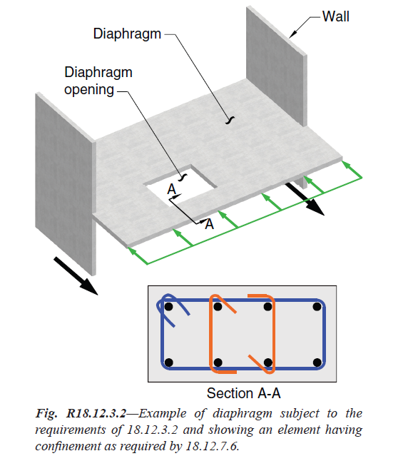
Fig. R18.12.3.2—Example of diaphragm subject to the | |
| requirements of 18.12.3.2 and showing an element having | |
| confinement as required by 18.12.7.6. | |
| | |
| American Concrete Institute – Copyrighted © Material – www.concrete.org | |
| PART 5: EARTHQUAKE RESISTANCE 337 | |
| 18 Seismic | |
| No further reproduction or distribution is permitted. | |
| | |
== 18.12.4 Cast-in-place composite topping slab diaphragms | |
=== 18.12.4.1 A cast-in-place composite topping slab on | |
| a precast floor or roof shall be permitted as a structural | |
| diaphragm, provided the cast-in-place topping slab is reinforced | |
| and the surface of the previously hardened concrete | |
| on which the topping slab is placed is clean, free of laitance, | |
| and intentionally roughened. | |
| | |
== 18.12.5 Cast-in-place noncomposite topping slab | |
=== 18.12.5.1 A cast-in-place noncomposite topping on a precast | |
| floor or roof shall be permitted as a structural diaphragm, | |
| provided the cast-in-place topping slab acting alone is | |
| designed and detailed to resist the design earthquake forces. | |
| | |
== 18.12.6 Minimum thickness of diaphragms | |
=== 18.12.6.1 Concrete slabs and composite topping slabs | |
| serving as diaphragms used to transmit earthquake forces shall | |
| be at least 50 mm thick. Topping slabs placed over precast | |
=== 18.12.6.1 Continuation | |
| floor or roof elements, acting as diaphragms and not relying | |
| on composite action with the precast elements to resist the | |
| design earthquake forces, shall be at least 65 mm thick. | |
| | |
== R18.12.4 Cast-in-place composite topping slab diaphragms | |
| | |
=== R18.12.4.1 A bonded topping slab is required so that | |
| the floor or roof system can provide restraint against slab | |
| buckling. Reinforcement is required to ensure the continuity | |
| of the shear transfer across precast joints. The connection | |
| requirements are introduced to promote a complete system | |
| with necessary shear transfers. | |
| | |
== R18.12.5 Cast-in-place noncomposite topping slab | |
| | |
=== R18.12.5.1 Composite action between the topping slab | |
| and the precast floor elements is not required, provided that | |
| the topping slab is designed to resist the design earthquake | |
| forces. | |
| | |
== R18.12.6 Minimum thickness of diaphragms | |
| | |
=== R18.12.6.1 The minimum thickness of concrete | |
| diaphragms reflects current practice in joist and waffle | |
| systems and composite topping slabs on precast floor and | |
=== R18.12.6.1 Continuation | |
| roof systems. Thicker slabs are required if the topping slab | |
| is not designed to act compositely with the precast system to | |
| resist the design earthquake forces. | |
| | |
| American Concrete Institute – Copyrighted © Material – www.concrete.org | |
| 338 ACI 318-19: BUILDING CODE REQUIREMENTS FOR STRUCTURAL CONCRETE | |
| No further reproduction or distribution is permitted. | |
| | |
== 18.12.7 Reinforcement | |
=== 18.12.7.1 The minimum reinforcement ratio for | |
| diaphragms shall be in conformance with 24.4. Except for | |
| post-tensioned slabs, reinforcement spacing each way in | |
| floor or roof systems shall not exceed 450 mm. Where welded | |
| wire reinforcement is used as the distributed reinforcement | |
| to resist shear in topping slabs placed over precast floor and | |
| roof elements, the wires parallel to the joints between the | |
| precast elements shall be spaced not less than 250 mm. on | |
| center. Reinforcement provided for shear strength shall be | |
| continuous and shall be distributed uniformly across the | |
| shear plane. | |
=== 18.12.7.2 Bonded tendons used as reinforcement to resist | |
| collector forces, diaphragm shear, or flexural tension shall be | |
| designed such that the stress due to design earthquake forces | |
| does not exceed 420 MPa. Precompression from unbonded | |
| tendons shall be permitted to resist diaphragm design forces | |
| if a seismic load path is provided. | |
=== 18.12.7.3 All reinforcement used to resist collector forces, | |
| diaphragm shear, or flexural tension shall be developed or | |
| spliced for fy in tension. | |
=== 18.12.7.4 Type 2 splices are required where mechanical | |
| splices on Grade 420 reinforcement are used to transfer | |
| forces between the diaphragm and the vertical elements of | |
| the seismic-force-resisting system. Grade 550 and Grade | |
| 690 reinforcement shall not be mechanically spliced for this | |
| application. | |
=== 18.12.7.5 Longitudinal reinforcement for collectors shall | |
| be proportioned such that the average tensile stress over | |
| length (a) or (b) does not exceed ϕfy where the value of fy is | |
| limited to 420 MPa. | |
=== 18.12.7.5 Continuation | |
| (a) Length between the end of a collector and location at | |
| which transfer of load to a vertical element begins | |
| (b) Length between two vertical elements | |
| | |
| | |
== R18.12.7 Reinforcement | |
| | |
=== R18.12.7.1 Minimum reinforcement ratios for diaphragms | |
| correspond to the required amount of temperature and | |
| shrinkage reinforcement (refer to 24.4). The maximum | |
| spacing for reinforcement is intended to control the width | |
| of inclined cracks. Minimum average prestress requirements | |
| (refer to 24.4.4.1) are considered to be adequate to limit the | |
| crack widths in post-tensioned floor systems; therefore, the | |
| maximum spacing requirements do not apply to these systems. | |
| The minimum spacing requirement for welded wire reinforcement | |
| in topping slabs on precast floor systems is to avoid | |
| fracture of the distributed reinforcement during an earthquake. | |
| Cracks in the topping slab open immediately above the | |
| boundary between the flanges of adjacent precast members, and | |
| the wires crossing those cracks are restrained by the transverse | |
| wires (Wood et al. 2000). Therefore, all the deformation associated | |
| with cracking should be accommodated in a distance not | |
| greater than the spacing of the transverse wires. A minimum | |
| spacing of 250 mm for the transverse wires is required to reduce | |
| the likelihood of fracture of the wires crossing the critical cracks | |
| during a design earthquake. The minimum spacing requirements | |
| do not apply to diaphragms reinforced with individual | |
| bars, because strains are distributed over a longer length. | |
| | |
=== R18.12.7.3 Bar development and lap splices are designed | |
| according to requirements of Chapter 25 for reinforcement | |
| in tension. Reductions in development or splice length for | |
| calculated stresses less than fy are not permitted, as indicated | |
| in 25.4.10.2. | |
| | |
=== R18.12.7.5 Table 20.2.2.4(a) permits the maximum design | |
| yield strength to be 550 MPa for portions of a collector, for | |
| example, at and near critical sections. The average stress | |
| in the collector is limited to control diaphragm cracking | |
| over the length of the collector. The calculation of average | |
| stress along the length is not necessary if the collector is | |
=== R18.12.7.5 Continuation | |
| designed for fy of 420 MPa even if Grade 550 reinforcement | |
| is specified. | |
| | |
| American Concrete Institute – Copyrighted © Material – www.concrete.org | |
| PART 5: EARTHQUAKE RESISTANCE 339 | |
| 18 Seismic | |
| No further reproduction or distribution is permitted. | |
| | |
| | |
=== 18.12.7.6 Collector elements with compressive stresses | |
| exceeding 0.2fc′ at any section shall have transverse reinforcement | |
| satisfying 18.7.5.2(a) through (e) and 18.7.5.3, | |
| except the spacing limit of 18.7.5.3(a) shall be one-third of | |
| the least dimension of the collector. The amount of transverse | |
| reinforcement shall be in accordance with Table 18.12.7.6. | |
| The specified transverse reinforcement is permitted to be | |
| discontinued at a section where the calculated compressive | |
| stress is less than 0.15fc′. | |
| If design forces have been amplified to account for the | |
| overstrength of the vertical elements of the seismic-forceresisting | |
| system, the limit of 0.2fc′ shall be increased to | |
| 0.5fc′, and the limit of 0.15fc′ shall be increased to 0.4fc′. | |
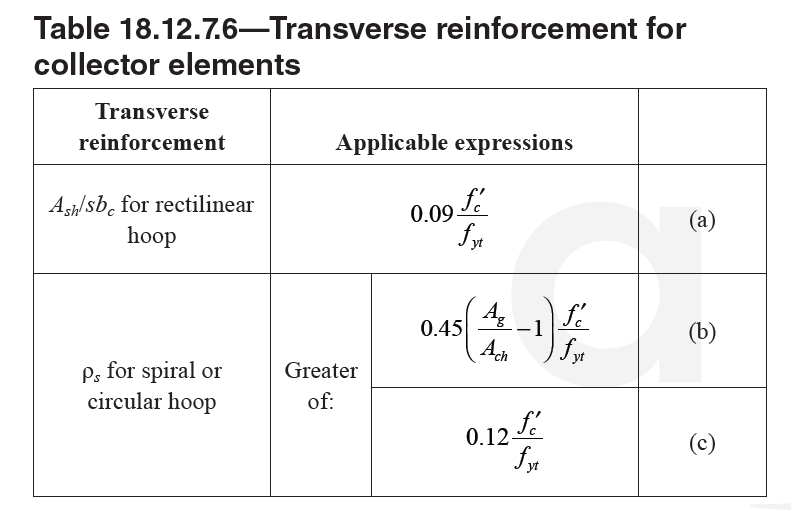
Table 18.12.7.6—Transverse reinforcement for | |
| | |
| | |
=== 18.12.7.7 Longitudinal reinforcement detailing for collector | |
| elements at splices and anchorage zones shall satisfy (a) or (b): | |
| |
| (a) Center-to-center spacing of at least three longitudinal | |
| bar diameters, but not less than 40 mm, and concrete clear | |
| cover of at least two and one-half longitudinal bar diameters, | |
| but not less than 50 mm. | |
| (b) Area of transverse reinforcement, providing Av at least | |
| the greater of 0.062 �sqrt(fc')(bw.s/fyt) and 0.35bw.s/fyt, except | |
| as required in 18.12.7.6 | |
| | |
== 18.12.8 Flexural strength | |
=== 18.12.8.1 Diaphragms and portions of diaphragms shall | |
| be designed for flexure in accordance with Chapter 12. The | |
| effects of openings shall be considered. | |
| | |
| | |
| | |
=== R18.12.7.6 In documents such as the NEHRP Provisions | |
| (FEMA P750), ASCE/SEI 7, the 2018 IBC, and the | |
| Uniform Building Code (ICBO 1997), collector elements | |
| of diaphragms are designed for forces amplified by a factor | |
| Ωo to account for the overstrength in the vertical elements | |
| of the seismic-force-resisting systems. The amplification | |
| factor Ωo ranges between 2 and 3 for most concrete structures, | |
| depending on the document selected and on the type | |
| of seismic-force-resisting system. In some documents, the | |
| factor can be calculated based on the maximum forces that | |
| can be developed by the elements of the vertical seismicforce- | |
| resisting system. | |
| Compressive stress calculated for the factored forces on a | |
| linearly elastic model based on gross section of the structural | |
| diaphragm is used as an index value to determine whether | |
| confining reinforcement is required. A calculated compressive | |
| stress of 0.2fc′, or 0.5fc′ for forces amplified by Ωo, | |
| is assumed to indicate that integrity of the entire structure | |
| depends on the ability of that member to resist substantial | |
| compressive force under severe cyclic loading. Transverse | |
| reinforcement is required at such locations to provide | |
| confinement for the concrete and the reinforcement. | |
| | |
=== R18.12.7.7 This section is intended to reduce the possibility | |
| of bar buckling and provide adequate bar development | |
| conditions in the vicinity of splices and anchorage zones. | |
| | |
== R18.12.8 Flexural strength | |
=== R18.12.8.1 Flexural strength for diaphragms is calculated | |
| using the same assumptions as for walls, columns, or beams. | |
| The design of diaphragms for flexure and other actions uses | |
| the applicable load combinations of 5.3.1 to consider earthquake | |
| forces acting concurrently with gravity or other loads. | |
| The influence of slab openings on flexural and shear strength | |
| is to be considered, including evaluating the potential critical | |
| sections created by the openings. The strut-and-tie method is | |
| potentially useful for designing diaphragms with openings. | |
=== R18.12.8.1 Continuation | |
| Earlier design practice assumed design moments for | |
| diaphragms were resisted entirely by chord forces acting | |
| at opposite edges of the diaphragm. This idealization was | |
| implicit in earlier versions of the Code, but has been replaced | |
| by an approach in which all longitudinal reinforcement, | |
| within the limits of 18.12.7, is assumed to contribute to the | |
| flexural strength of the diaphragm. This change reduces the | |
| required area of longitudinal reinforcement concentrated | |
| near the edge of the diaphragm, but should not be interpreted | |
| as a requirement to eliminate all boundary reinforcement. | |
| | |
| | |
| American Concrete Institute – Copyrighted © Material – www.concrete.org | |
| 340 ACI 318-19: BUILDING CODE REQUIREMENTS FOR STRUCTURAL CONCRETE | |
| No further reproduction or distribution is permitted. | |
| | |
| | |
== 18.12.9 Shear strength | |
=== 18.12.9.1 Vn of diaphragms shall not exceed: | |
| Vn = Acv ( 0.17.λ.sqrt(fc')�+rho_t.fy ) ... (18.12.9.1) | |
| For cast-in-place topping slab diaphragms on precast | |
| floor or roof members, Acv shall be calculated using only | |
| the thickness of topping slab for noncomposite topping slab | |
| diaphragms and the combined thickness of cast-in-place and | |
| precast elements for composite topping slab diaphragms. For | |
| composite topping slab diaphragms, the value of fc′ used to | |
| calculate Vn shall not exceed the lesser of fc′ for the precast | |
| members and fc′ for the topping slab. | |
| | |
| 18.12.9.2 Vn of diaphragms shall not exceed 0.66 sqrt(fc') Acv. | |
| | |
=== 18.12.9.3 Above joints between precast elements in | |
| noncomposite and composite cast-in-place topping slab | |
| diaphragms, Vn shall not exceed: | |
| |
| Vn = Avf.fy.μ ... (18.12.9.3) | |
| |
| where Avf is the total area of shear friction reinforcement | |
| within the topping slab, including both distributed and | |
| boundary reinforcement, that is oriented perpendicular to | |
| joints in the precast system and coefficient of friction, μ, | |
| is 1.0λ, where λ is given in 19.2.4. At least one-half of Avf | |
| shall be uniformly distributed along the length of the potential | |
| shear plane. The area of distributed reinforcement in the | |
| topping slab shall satisfy 24.4.3.2 in each direction. | |
=== 18.12.9.4 Above joints between precast elements in | |
| noncomposite and composite cast-in-place topping slab | |
| diaphragms, Vn shall not exceed the limits in 22.9.4.4, where | |
| Ac is calculated using only the thickness of the topping slab. | |
| | |
| | |
| | |
== R18.12.9 Shear strength | |
| The shear strength requirements for diaphragms are | |
| similar to those for slender structural walls and are based | |
| on the shear provisions for beams. The term Acv refers to the | |
| gross area of the diaphragm, but may not exceed the thickness | |
| times the width of the diaphragm. This corresponds | |
| to the gross area of the effective deep beam that forms | |
| the diaphragm. Distributed slab reinforcement ρt used to | |
| calculate shear strength of a diaphragm in Eq. (18.12.9.1) | |
| is positioned perpendicular to the diaphragm flexural reinforcement. | |
| Provision 18.12.9.2 limits the maximum shear | |
| strength of the diaphragm. | |
| In addition to satisfying 18.12.9.1 and 18.12.9.2, cast-inplace | |
| topping slab diaphragms must also satisfy 18.12.9.3 | |
| and 18.12.9.4. Cast-in-place topping slabs on a precast floor | |
| or roof system tend to have shrinkage cracks that are aligned | |
| with the joints between adjacent precast members. Therefore, | |
| the additional shear strength requirements for topping | |
| slab diaphragms in 18.12.9.3 are based on a shear friction | |
| model (Wood et al. 2000), and the assumed crack plane | |
| corresponds to joints in the precast system along the direction | |
| of the applied shear, as shown in Fig. R22.9.4.3a. The | |
| coefficient of friction, μ, in the shear friction model is taken | |
| equal to 1.0 for normalweight concrete due to the presence | |
| of these shrinkage cracks. | |
| Both distributed and boundary reinforcement in the topping | |
| slab may be considered as shear friction reinforcement Avf. | |
| Boundary reinforcement within the diaphragm was called | |
| chord reinforcement in ACI 318 before 2008. Although the | |
| boundary reinforcement also resists forces due to moment | |
| and axial force in the diaphragm, the reduction in the shear | |
| friction resistance in the tension zone is offset by the increase | |
| in shear friction resistance in the compression zone. Therefore, | |
| the area of boundary reinforcement used to resist shear | |
| friction need not be added to the area of boundary reinforcement | |
| used to resist moment and axial force. The distributed | |
| topping slab reinforcement must contribute at least one-half | |
| of the nominal shear strength. It is assumed that connections | |
| between the precast elements do not contribute to the shear | |
| strength of the topping slab diaphragm. | |
| Provision 18.12.9.4 limits the maximum shear that may be | |
| transmitted by shear friction within a topping slab diaphragm. | |
| | |
| | |
| American Concrete Institute – Copyrighted © Material – www.concrete.org | |
| PART 5: EARTHQUAKE RESISTANCE 341 | |
| 18 Seismic | |
| No further reproduction or distribution is permitted. | |
| | |
== 18.12.10 Construction joints | |
=== 18.12.10.1 Construction joints in diaphragms shall be | |
| specified according to 26.5.6, and contact surfaces shall be | |
| roughened consistent with condition (b) of Table 22.9.4.2. | |
| | |
== 18.12.11 Precast concrete diaphragms | |
=== 18.12.11.1 Diaphragms and collectors constructed using | |
| precast concrete members with composite topping slab | |
| and not satisfying 18.12.4, and untopped precast concrete | |
| diaphragms, are permitted provided they satisfy the requirements | |
| of ACI 550.5M. Cast-in-place noncomposite topping | |
| slab diaphragms shall satisfy 18.12.5 and 18.12.6. | |
=== 18.12.11.2 Connections and reinforcement at joints used | |
| in the construction of precast concrete diaphragms satisfying | |
| 18.12.11.1 shall have been tested in accordance with ACI | |
| 550.4M. | |
=== 18.12.11.3 Extrapolation of data on connections and | |
| reinforcement at joints to project details that result in larger | |
| construction tolerances than those used to qualify connections | |
| in accordance with ACI 550.4M shall not be permitted. | |
| | |
== R18.12.11 Precast concrete diaphragms | |
=== R18.12.11.1 ACI 550.5M provides requirements for the | |
| design of precast concrete diaphragms with connections | |
| whose performance has been validated by ACI 550.4M | |
| testing. ACI 550.5M permits a maximum tolerance for positioning | |
| and completion of connections of 13 mm, which can | |
| be difficult to achieve with normal construction practices. | |
| Section 26.13.1.3 requires continuous inspection of precast | |
| concrete diaphragm connections to verify that construction | |
| is performed properly and tolerances not greater than 13 mm | |
| for all connections are achieved. Results from ACI 550.4M | |
| testing are not to be extrapolated to allow greater tolerances. | |
| Topped precast concrete floors designed in accordance | |
| with Chapter 18 need careful consideration of support conditions | |
| to verify precast concrete members have sufficient | |
| seating for anticipated displacements and ability to accommodate | |
| relative rotations between beam supports and the | |
| member (Henry et al. 2017). | |
| | |
== 18.12.12 Structural trusses | |
=== 18.12.12.1 Structural truss elements with compressive | |
| stresses exceeding 0.2fc′ at any section shall have transverse | |
| reinforcement, in accordance with 18.7.5.2, 18.7.5.3, 18.7.5.7, | |
| and Table 18.12.12.1, over the length of the element. | |
| | |
== R18.12.12 Structural trusses | |
=== R18.12.12.1 The expressions for transverse reinforcement | |
| Ash are based on ensuring compression capacity of an equivalent | |
| column section is maintained after spalling of cover | |
| concrete. | |
| | |
| | |
| American Concrete Institute – Copyrighted © Material – www.concrete.org | |
| 342 ACI 318-19: BUILDING CODE REQUIREMENTS FOR STRUCTURAL CONCRETE | |
| No further reproduction or distribution is permitted. | |
| | |
| | |
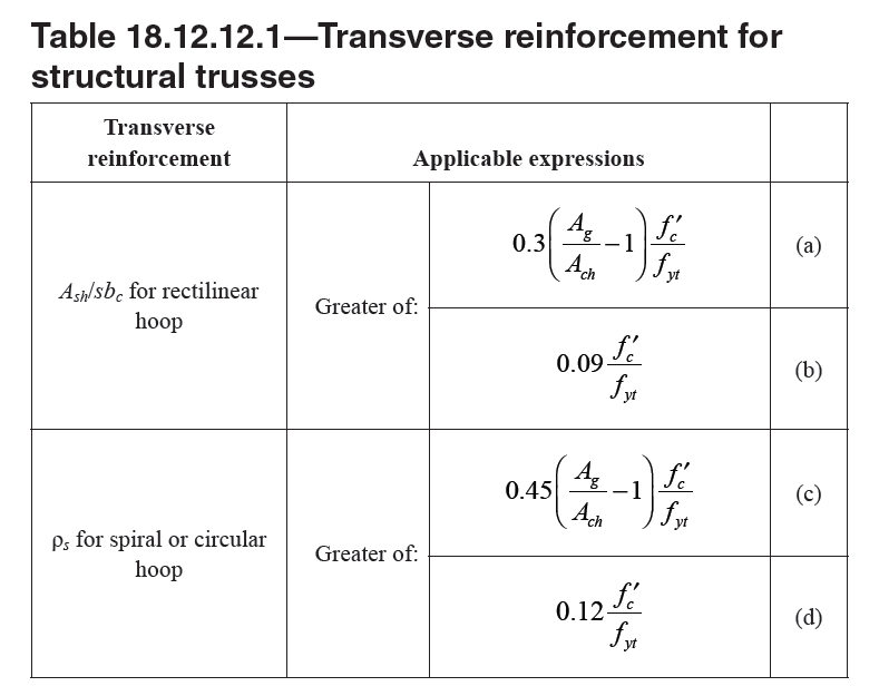
Table 18.12.12.1—Transverse reinforcement for | |
| structural trusses_ | |
| | |
=== 18.12.12.2 All continuous reinforcement in structural | |
| truss elements shall be developed or spliced for fy in tension. | |
| | |
[ Lanjut Ke 18.13—Foundations ... ] | |
| |
| |
| |