| |
| |
= 18. CHAPTER 18 — EARTHQUAKE-RESISTANT STRUCTURES | |
= 18.10 — Special structural walls | |
== 18.10.1 Scope | |
=== 18.10.1.1 This section shall apply to special structural | |
| walls, including ductile coupled walls, and all components | |
| of special structural walls including coupling beams and | |
| wall piers forming part of the seismic-force-resisting system. | |
=== 18.10.1.2 Special structural walls constructed using | |
| precast concrete shall be in accordance with 18.11 in addition | |
| to 18.10. | |
= R18.10 — Special structural walls | |
== R18.10.1 Scope | |
| This section contains requirements for the dimensions | |
| and details of special structural walls and all components | |
| including coupling beams and wall piers. Wall piers are | |
| defined in Chapter 2. Design provisions for vertical wall | |
| segments depend on the aspect ratio of the wall segment | |
| in the plane of the wall (hw/ℓw), and the aspect ratio of the | |
| horizontal cross section (ℓw/bw), and generally follow the | |
| descriptions in Table R18.10.1 . The limiting aspect ratios for | |
| wall piers are based on engineering judgment. It is intended | |
| that flexural yielding of the vertical reinforcement in the pier | |
| should limit shear demand on the pier. | |
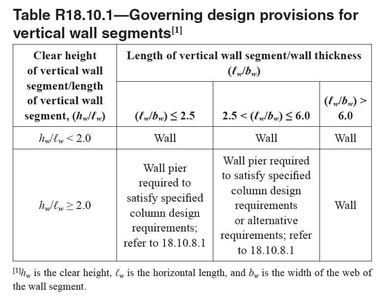
Table R18.10.1—Governing design provisions for | |
| vertical wall segments[1]_ | |
| | |
== 18.10.2 Reinforcement | |
=== 18.10.2.1 The distributed web reinforcement ratios, ρℓ and | |
| ρt, for structural walls shall be at least 0.0025, except that | |
| if Vu does not exceed 0.083λ sqrt(fc') Acv, ρt shall be permitted | |
| to be reduced to the values in 11.6. Reinforcement spacing | |
| each way in structural walls shall not exceed 450 mm. Reinforcement | |
| contributing to Vn shall be continuous and shall | |
| be distributed across the shear plane. | |
=== 18.10.2.2 At least two curtains of reinforcement shall be | |
| used in a wall if Vu > 0.17λ sqrt(fc') Acv or hw/ℓw ≥ 2.0, in which hw | |
| and ℓw refer to height and length of entire wall, respectively. | |
| | |
== R18.10.2 Reinforcement | |
| Minimum reinforcement requirements in 18.10.2.1 follow | |
| from preceding Codes. The requirement for distributed shear | |
| reinforcement is related to the intent to control the width of | |
| inclined cracks. The requirement for two layers of reinforcement | |
| in walls resisting substantial design shears in 18.10.2.2 | |
| is based on the observation that, under ordinary construction | |
| conditions, the probability of maintaining a single layer of | |
| reinforcement near the middle of the wall section is quite | |
| low. Furthermore, presence of reinforcement close to the | |
| surface tends to inhibit fragmentation of the concrete in the | |
| event of severe cracking during an earthquake. The requirement | |
| for two layers of vertical reinforcement in more slender | |
| walls is to improve lateral stability of the compression zone | |
| under cyclic loads following yielding of vertical reinforcement | |
| in tension. | |
| | |
| | |
| American Concrete Institute – Copyrighted © Material – www.concrete.org | |
| PART 5: EARTHQUAKE RESISTANCE 317 | |
| 18 Seismic | |
| No further reproduction or distribution is permitted. | |
| | |
=== 18.10.2.3 Reinforcement in structural walls shall be developed | |
| or spliced for fy in tension in accordance with 25.4, | |
| 25.5, and (a) through (d): | |
| |
| (a) Except at the top of a wall, longitudinal reinforcement | |
| shall extend at least 3.6 m above the point at which it is no | |
| longer required to resist flexure but need not extend more | |
| than ℓd above the next floor level. | |
| (b) At locations where yielding of longitudinal reinforcement | |
| is likely to occur as a result of lateral displacements, | |
| development lengths of longitudinal reinforcement shall | |
| be 1.25 times the values calculated for fy in tension. | |
| (c) Lap splices of longitudinal reinforcement within | |
| boundary regions shall not be permitted over a height | |
| equal to hsx above, and ℓd below, critical sections where | |
| yielding of longitudinal reinforcement is likely to occur | |
| as a result of lateral displacements. The value of hsx need | |
| not exceed 6 m. Boundary regions include those within | |
| lengths specified in 18.10.6.4(a) and within a length equal | |
| to the wall thickness measured beyond the intersecting | |
| region(s) of connected walls. | |
| (d) Mechanical splices of reinforcement shall conform to | |
| 18.2.7 and welded splices of reinforcement shall conform | |
| to 18.2.8. | |
| | |
=== R18.10.2.3 Requirements are based on provisions in | |
| Chapter 25, with modifications to address issues specific | |
| to structural walls, as well as to the use of high-strength | |
| reinforcement. Because actual forces in longitudinal reinforcement | |
| of structural walls may exceed calculated forces, | |
| reinforcement should be developed or spliced to reach the | |
| yield strength of the bar in tension. Termination of longitudinal | |
| (vertical) reinforcement in structural walls should be | |
| specified so that bars extend above elevations where they are | |
| no longer required to resist design flexure and axial force; | |
| extending bars ℓd above the next floor level is a practical | |
| approach to achieving this requirement. A limit of 3.6 m | |
| is included for cases with large story heights. Bar terminations | |
| should be accomplished gradually over a wall height | |
| and should not be located close to critical sections where | |
| yielding of longitudinal reinforcement is expected, which | |
| typically occurs at the base of a wall with a uniform, or | |
| nearly uniform, cross section over the building height. Strain | |
| hardening of reinforcement results in spread of plasticity | |
| away from critical sections as lateral deformations increase. | |
| Research (Aaletti et al. 2012; Hardisty et al. 2015) shows | |
| that lap splices should be avoided in walls where flexural | |
| yielding is anticipated, for example at the base of walls, | |
| because they may lead to large localized strains and bar fractures. | |
| !!Figure R18.10.2.3 illustrates boundary regions where | |
| lap splices are not permitted. | |
| At locations where yielding of longitudinal reinforcement | |
| is expected, a 1.25 multiplier is applied to account for the | |
| likelihood that the actual yield strength exceeds the specified | |
| yield strength of the bar, as well as the influence of | |
| strain hardening and cyclic load reversals. Where transverse | |
| reinforcement is used, development lengths for straight and | |
| hooked bars may be reduced as permitted in 25.4.2 and | |
| 25.4.3, respectively, because closely spaced transverse reinforcement | |
| improves the performance of splices and hooks | |
| subjected to repeated inelastic demands (ACI 408.2R). | |
| | |
| American Concrete Institute – Copyrighted © Material – www.concrete.org | |
| 318 ACI 318-19: BUILDING CODE REQUIREMENTS FOR STRUCTURAL CONCRETE | |
| No further reproduction or distribution is permitted. | |
| | |
| | |
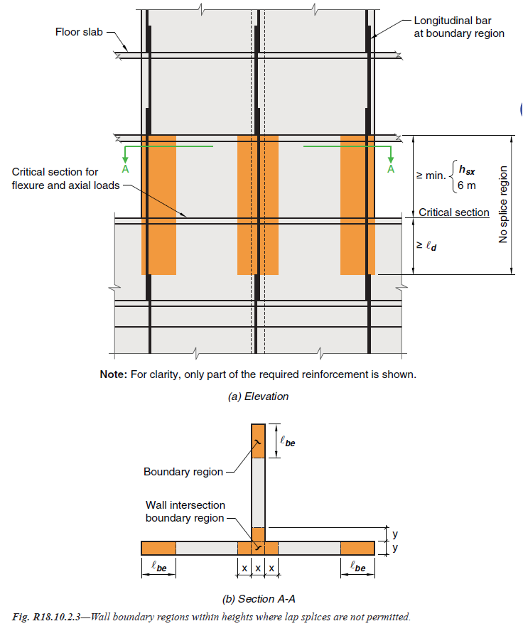
Fig. R18.10.2.3—Wall boundary regions within heights where lap splices are not permitted. | |
| | |
=== 18.10.2.4 Walls or wall piers with hw/ℓw ≥ 2.0 that are | |
| effectively continuous from the base of structure to top of | |
| wall and are designed to have a single critical section for | |
| flexure and axial loads shall have longitudinal reinforcement | |
| at the ends of a vertical wall segment that satisfies (a) | |
| through (c). | |
| | |
=== R18.10.2.4 This provision is based on the assumption that | |
| inelastic response of the wall is dominated by flexural action | |
| at a critical, yielding section. The wall should be proportioned | |
| so that the critical section occurs where intended. | |
| If there is potential for more than one critical section, it is | |
| prudent to provide the minimum boundary reinforcement at | |
| all such sections. | |
| | |
| American Concrete Institute – Copyrighted © Material – www.concrete.org | |
| PART 5: EARTHQUAKE RESISTANCE 319 | |
| 18 Seismic | |
| No further reproduction or distribution is permitted. | |
| | |
=== 18.10.2.4 continuation | |
| (a) Longitudinal reinforcement ratio within 0.15ℓw from | |
| the end of a vertical wall segment, and over a width equal | |
| to the wall thickness, shall be at least 0.5 sqrt(fc')/fy . | |
| (b) The longitudinal reinforcement required by 18.10.2.4(a) | |
| shall extend vertically above and below the critical section | |
| at least the greater of ℓw and Mu/3Vu. | |
| (c) No more than 50 percent of the reinforcement required | |
| by 18.10.2.4(a) shall be terminated at any one section. | |
| | |
=== R18.10.2.4 continuation | |
| The requirement for minimum longitudinal reinforcement | |
| in the ends of the wall is to promote the formation of | |
| well-distributed secondary flexural cracks in the wall plastic | |
| hinge region to achieve the required deformation capacity | |
| during earthquakes (Lu et al. 2017; Sritharan et al. 2014). | |
| Furthermore, significantly higher in-place concrete strengths | |
| than used in design calculations may be detrimental to the | |
| distribution of cracking. 18.10.2.4(a) specifies the required | |
| reinforcement ratio in the end tension zones, as shown for | |
| different wall sections in Fig. R18.10.2.4 . | |
| The longitudinal reinforcement required by 18.10.2.4(a) | |
| should be located at a critical section where concentrated | |
| yielding of longitudinal reinforcement is expected (typically | |
| the base of a cantilever wall) and must continue to a sufficient | |
| elevation of the wall to avoid a weak section adjacent | |
| to the intended plastic hinge region. A height above or below | |
| the critical section of Mu/3Vu is used to identify the length | |
| over which yielding is expected. | |
| | |
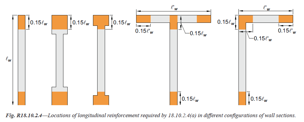
Fig. R18.10.2.4—Locations of longitudinal reinforcement required by 18.10.2.4(a) in different configurations of wall sections. | |
| | |
=== 18.10.2.5 Reinforcement in coupling beams shall be developed | |
| for fy in tension in accordance with 25.4, 25.5, and (a) | |
| and (b): | |
| | |
| (a) If coupling beams are reinforced according to 18.6.3.1, | |
| the development length of longitudinal reinforcement | |
| shall be 1.25 times the values calculated for fy in tension. | |
| (b) If coupling beams are reinforced according to 18.10.7.4, | |
| the development length of diagonal reinforcement shall be | |
| 1.25 times the values calculated for fy in tension. | |
| | |
== 18.10.3 Design forces | |
== R18.10.3 Design forces | |
| The possibility of yielding in components of structural | |
| walls should be considered, as in the portion of a wall between | |
| two window openings, in which case the actual shear may be | |
| in excess of the shear indicated by lateral load analysis based | |
| on factored design forces. | |
| | |
| American Concrete Institute – Copyrighted © Material – www.concrete.org | |
| 320 ACI 318-19: BUILDING CODE REQUIREMENTS FOR STRUCTURAL CONCRETE | |
| No further reproduction or distribution is permitted. | |
| | |
=== 18.10.3.1 The design shear force Ve shall be calculated by: | |
| Ve = Ωv.ωv.Vu ≤ 3Vu (18.10.3.1) | |
| where Vu, Ωv, and ωv are defined in 18.10.3.1.1, 18.10.3.1.2, | |
| and 18.10.3.1.3, respectively. | |
==== 18.10.3.1.1 Vu is the shear force obtained from code lateral | |
| load analysis with factored load combinations. | |
==== 18.10.3.1.2 Ωv shall be in accordance with | |
| Table 18.10.3.1.2 . | |
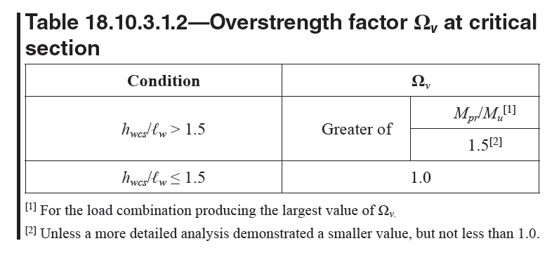
Table 18.10.3.1.2—Overstrength factor Ωv at critical | |
| section_ | |
| | |
==== 18.10.3.1.3 For walls with hwcs/ℓw < 2.0, ωv shall be taken | |
| as 1.0. Otherwise, ωv shall be calculated as: | |
| |
| ωv = 0.9 + ns/10, ns <=6 | |
| |
| ωv = 1.3 + ns/30 <=1.8, ns > 6 | |
| |
| (18.10.3.1.3) | |
| |
| where ns shall not be taken less than the quantity 0.00028.hwcs. | |
| | |
| | |
=== R18.10.3.1 Design shears for structural walls are obtained | |
| from lateral load analysis with appropriate load factors | |
| increased to account for: (i) flexural overstrength at critical | |
| sections where yielding of longitudinal reinforcement is | |
| expected; and (ii) dynamic amplification due to higher mode | |
| effects, as illustrated in Fig. R18.10.3.1 . The approach used | |
| to determine the amplified shear forces is similar to that used | |
| in New Zealand Standard 3101 (2006). Because Mn and Mpr | |
| depend on axial force, which varies for different load combinations, | |
| and loading direction for flanged and coupled walls, | |
| the condition producing the largest value of Ωv should be | |
| used. Although the value of 1.5 in 18.10.3.1.2 is greater than | |
| the minimum value obtained for the governing load combination | |
| with a ϕ factor of 0.9 and a tensile stress of at least 1.25fy | |
| in the longitudinal reinforcement, a value greater than 1.5 may | |
| be appropriate if provided longitudinal reinforcement exceeds | |
| that required. Dynamic amplification is not significant in | |
| walls with hw/ℓw < 2. A limit of 0.007hwcs is imposed on ns to | |
| account for buildings with large story heights. The application | |
| of ΩV to Vu does not preclude the application of a redundancy | |
| factor if required by the general building code. | |
| | |
| American Concrete Institute – Copyrighted © Material – www.concrete.org | |
| PART 5: EARTHQUAKE RESISTANCE 321 | |
| 18 Seismic | |
| No further reproduction or distribution is permitted. | |
| | |
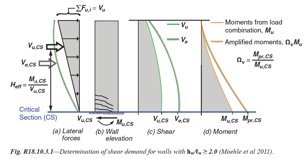
Fig. R18.10.3.1—Determination of shear demand for walls with hw/ℓw ≥ 2.0 (Moehle et al 2011). | |
| | |
== 18.10.4 Shear strength | |
=== 18.10.4.1 Vn shall be calculated by: | |
| Vn = (αc.lambda.sqrt(fc') + rho_t.fyt) Acv ... (18.10.4.1) | |
| where: | |
| αc = 0.25 for hw/ℓw ≤ 1.5 | |
| αc = 0.17 for hw/ℓw ≥ 2.0 | |
| It shall be permitted to linearly interpolate the value of αc | |
| between 0.25 and 0.17 for 1.5 < hw/ℓw < 2.0. | |
=== 18.10.4.2 In 18.10.4.1, the value of ratio hw/ℓw used to | |
| calculate Vn for segments of a wall shall be the greater of the | |
| ratios for the entire wall and the segment of wall considered. | |
=== 18.10.4.3 Walls shall have distributed shear reinforcement | |
| in two orthogonal directions in the plane of the wall. If hw/ℓw | |
| does not exceed 2.0, reinforcement ratio ρℓ shall be at least | |
| the reinforcement ratio ρt. | |
=== 18.10.4.4 For all vertical wall segments sharing a common | |
| lateral force, Vn shall not be taken greater than 0.66 �sqrt(fc') Acv. | |
| For any one of the individual vertical wall segments, Vn shall | |
| not be taken greater than 0.83 �sqrt(fc') Acw, where Acw is the area | |
| of concrete section of the individual vertical wall segment | |
| considered. | |
=== 18.10.4.5 For horizontal wall segments and coupling | |
| beams, Vn shall not be taken greater than 0.83 �sqrt(fc') Acv, | |
| where Acw is the area of concrete section of a horizontal wall | |
| segment or coupling beam. | |
| | |
== R18.10.4 Shear strength | |
| Equation (18.10.4.1) recognizes the higher shear strength | |
| of walls with high shear-to-moment ratios (Hirosawa 1977; | |
| Joint ACI-ASCE Committee 326 1962; Barda et al. 1977). | |
| The nominal shear strength is given in terms of the gross area | |
| of the section resisting shear, Acv. For a rectangular section | |
| without openings, the term Acv refers to the gross area of the | |
| cross section rather than to the product of the width and the | |
| effective depth. | |
| A vertical wall segment refers to a part of a wall bounded | |
| horizontally by openings or by an opening and an edge. For | |
| an isolated wall or a vertical wall segment, ρt refers to horizontal | |
| reinforcement and ρℓ refers to vertical reinforcement. | |
| The ratio hw/ℓw may refer to overall dimensions of a wall, | |
| or of a segment of the wall bounded by two openings, or an | |
| opening and an edge. The intent of 18.10.4.2 is to make certain | |
| that any segment of a wall is not assigned a unit strength | |
| greater than that for the entire wall. However, a wall segment | |
| with a ratio of hw/ℓw higher than that of the entire wall should | |
| be proportioned for the unit strength associated with the ratio | |
| hw/ℓw based on the dimensions for that segment. | |
| To restrain the inclined cracks effectively, reinforcement | |
| included in ρt and ρℓ should be appropriately distributed along | |
| the length and height of the wall (refer to 18.10.4.3). Chord | |
| reinforcement provided near wall edges in concentrated | |
| amounts for resisting bending moment is not to be included in | |
| determining ρt and ρℓ. Within practical limits, shear reinforcement | |
| distribution should be uniform and at a small spacing. | |
| If the factored shear force at a given level in a structure is | |
| resisted by several walls or several vertical wall segments of | |
| a perforated wall, the average unit shear strength assumed for | |
| the total available cross-sectional area is limited to 0.66 �sqrt(fc') | |
| with the additional requirement that the unit shear strength | |
| assigned to any single vertical wall segment does not exceed | |
| 0.83 �sqrt(fc') . The upper limit of strength to be assigned to any | |
| | |
| | |
| American Concrete Institute – Copyrighted © Material – www.concrete.org | |
| 322 ACI 318-19: BUILDING CODE REQUIREMENTS FOR STRUCTURAL CONCRETE | |
| No further reproduction or distribution is permitted. | |
| | |
== R18.10.4 continuation | |
| one member is imposed to limit the degree of redistribution | |
| of shear force. | |
| Horizontal wall segments in 18.10.4.5 refer to wall | |
| sections between two vertically aligned openings (refer | |
| to Fig. R18.10.4.5 ). It is, in effect, a vertical wall segment | |
| rotated through 90 degrees. A horizontal wall segment is also | |
| referred to as a coupling beam when the openings are aligned | |
| vertically over the building height. When designing a horizontal | |
| wall segment or coupling beam, ρt refers to vertical | |
| reinforcement and ρℓ refers to horizontal reinforcement. | |
| | |
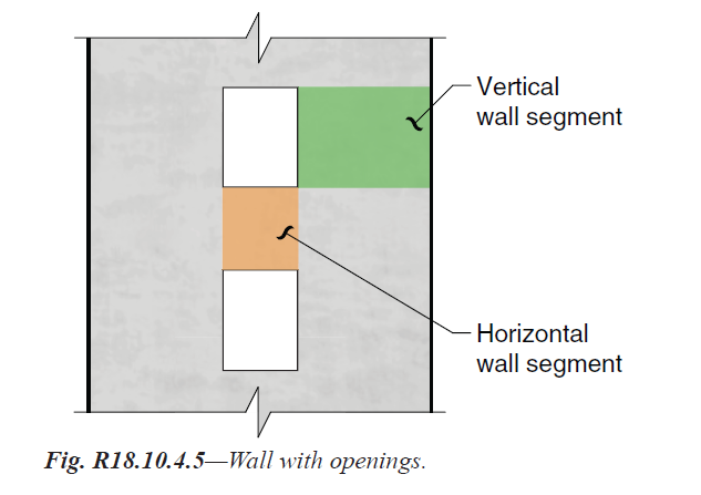
Fig. R18.10.4.5—Wall with openings. | |
| | |
| | |
=== 18.10.4.6 The requirements of 21.2.4.1 shall not apply to | |
| walls or wall piers designed according to 18.10.6.2. | |
=== R18.10.4.6 Section 21.2.4.1 does not apply because walls | |
| designed according to 18.10.6.2 are controlled by flexural | |
| yielding, and code level shear forces have been amplified. | |
| | |
== 18.10.5 Design for flexure and axial force | |
=== 18.10.5.1 Structural walls and portions of such walls | |
| subject to combined flexure and axial loads shall be designed | |
| in accordance with 22.4. Concrete and developed longitudinal | |
| reinforcement within effective flange widths, boundary | |
| elements, and the wall web shall be considered effective. | |
| The effects of openings shall be considered. | |
=== 18.10.5.2 Unless a more detailed analysis is performed, | |
| effective flange widths of flanged sections shall extend from | |
| the face of the web a distance equal to the lesser of one-half | |
| the distance to an adjacent wall web and 25 percent of the | |
| total wall height above the section under consideration. | |
| | |
| | |
== R18.10.5 Design for flexure and axial force | |
=== R18.10.5.1 Flexural strength of a wall or wall segment | |
| is determined according to procedures commonly used for | |
| columns. Strength should be determined considering the | |
| applied axial and lateral forces. Reinforcement concentrated | |
| in boundary elements and distributed in flanges and webs | |
| should be included in the strength calculations based on a | |
| strain compatibility analysis. The foundation supporting the | |
| wall should be designed to resist the wall boundary and web | |
| forces. For walls with openings, the influence of the opening | |
| or openings on flexural and shear strengths is to be considered | |
| and a load path around the opening or openings should | |
| be verified. Capacity-design concepts and the strut-and-tie | |
| method may be useful for this purpose (Taylor et al. 1998). | |
| | |
=== R18.10.5.2 Where wall sections intersect to form L-, | |
| T-, C-, or other cross-sectional shapes, the influence of the | |
| flange on the behavior of the wall should be considered by | |
| selecting appropriate flange widths. Tests (Wallace 1996) | |
| show that effective flange width increases with increasing | |
| drift level and the effectiveness of a flange in compression | |
| differs from that for a flange in tension. The value used for | |
| the effective compression flange width has little effect on | |
| | |
| | |
| American Concrete Institute – Copyrighted © Material – www.concrete.org | |
| PART 5: EARTHQUAKE RESISTANCE 323 | |
| 18 Seismic | |
| No further reproduction or distribution is permitted. | |
| | |
=== R18.10.5.2 continuation | |
| the strength and deformation capacity of the wall; therefore, | |
| to simplify design, a single value of effective flange width | |
| based on an estimate of the effective tension flange width is | |
| used in both tension and compression. | |
| | |
== 18.10.6 Boundary elements of special structural walls | |
=== 18.10.6.1 The need for special boundary elements at the | |
| edges of structural walls shall be evaluated in accordance | |
| with 18.10.6.2 or 18.10.6.3. The requirements of 18.10.6.4 | |
| and 18.10.6.5 shall also be satisfied. | |
| | |
== R18.10.6 Boundary elements of special structural walls | |
=== R18.10.6.1 Two design approaches for evaluating | |
| detailing requirements at wall boundaries are included in | |
| 18.10.6.1. Provision 18.10.6.2 allows the use of displacement- | |
| based design of walls, in which the structural details | |
| are determined directly on the basis of the expected lateral | |
| displacements of the wall. The provisions of 18.10.6.3 are | |
| similar to those of the 1995 Code, and have been retained | |
| because they are conservative for assessing required transverse | |
| reinforcement at wall boundaries for many walls. | |
| Provisions 18.10.6.4 and 18.10.6.5 apply to structural walls | |
| designed by either 18.10.6.2 or 18.10.6.3. | |
| | |
=== 18.10.6.2 Walls or wall piers with hwcs/ℓw ≥ 2.0 that are | |
| effectively continuous from the base of structure to top of | |
| wall and are designed to have a single critical section for | |
| flexure and axial loads shall satisfy (a) and (b): | |
| (a) Compression zones shall be reinforced with special | |
| boundary elements where_ | |
| |
| 1.5δu/hwcs >= lw/(600c) | |
| |
| (18.10.6.2a) | |
| and c corresponds to the largest neutral axis depth calculated | |
| for the factored axial force and nominal moment | |
| strength consistent with the direction of the design | |
| displacement δu. Ratio δu/hwcs shall not be taken less than | |
| 0.005. | |
| (b) If special boundary elements are required by (a), then | |
| (i) and either (ii) or (iii) shall be satisfied. | |
| (i) Special boundary element transverse reinforcement | |
| shall extend vertically above and below the critical | |
| section a least the greater of ℓw and Mu/4Vu, except as | |
| permitted in 18.10.6.4(i). | |
| (ii) b >= sqrt(0.025.c.lw) | |
| (iii) δc/hwcs ≥ 1.5δu/hwcs, where: | |
| |
| δc/hwcs=(1/400)[4-1/50(lw/b)(c/b)-Ve/(0.66.sqrt(fc').Acv)] | |
| |
| � (18.10.6.2b) | |
| |
| The value of δc/hwcs in Eq. (18.10.6.2b) need not be taken | |
| less than 0.015. | |
| | |
=== R18.10.6.2 This section is based on the assumption that | |
| inelastic response of the wall is dominated by flexural action | |
| at a critical, yielding section. The wall should be proportioned | |
| and reinforced so that the critical section occurs | |
| where intended. | |
| Equation (18.10.6.2a) follows from a displacementbased | |
| approach (Moehle 1992; Wallace and Orakcal 2002). | |
| The approach assumes that special boundary elements are | |
| required to confine the concrete where the strain at the | |
| extreme compression fiber of the wall exceeds a critical | |
| value when the wall is displaced to 1.5 times the design | |
| displacement. Consistent with a displacement-based design | |
| approach, the design displacement in Eq. (18.10.6.2a) is | |
| taken at the top of the wall, and the wall height is taken as | |
| the height above the critical section. The multiplier of 1.5 | |
| on design displacement was added to Eq. (18.10.6.2) in the | |
| 2014 Code to produce detailing requirements more consistent | |
| with the building code performance intent of a low probability | |
| of collapse in Maximum Considered Earthquake level | |
| shaking. The lower limit of 0.005 on the quantity δu/hwcs | |
| requires special boundary elements if wall boundary longitudinal | |
| reinforcement tensile strain does not reach approximately | |
| twice the limit used to define tension-controlled | |
| beam sections according to 21.2.2. The lower limit of 0.005 | |
| on the quantity δu/hwcs requires moderate wall deformation | |
| capacity for stiff buildings. | |
| The neutral axis depth c in Eq. (18.10.6.2) is the depth | |
| calculated according to 22.2 corresponding to development | |
| of nominal flexural strength of the wall when displaced in | |
| the same direction as δu. The axial load is the factored axial | |
| load that is consistent with the design load combination that | |
| produces the design displacement δu. | |
| The height of the special boundary element is based on | |
| estimates of plastic hinge length and extends beyond the | |
| zone over which yielding of tension reinforcement and | |
| spalling of concrete are likely to occur. | |
| | |
| American Concrete Institute – Copyrighted © Material – www.concrete.org | |
| 324 ACI 318-19: BUILDING CODE REQUIREMENTS FOR STRUCTURAL CONCRETE | |
| No further reproduction or distribution is permitted. | |
| | |
=== R18.10.6.2 continuation | |
| Equation (18.10.6.2b) is based on the mean top-of-wall | |
| drift capacity at 20 percent loss of lateral strength proposed | |
| by Abdullah and Wallace (2019). The requirement that drift | |
| capacity exceed 1.5 times the drift demand results in a low | |
| probability of strength loss for the design earthquake. The | |
| expression for b in (ii) is derived from Eq. (18.10.6.2b), | |
| assuming values of Vu/(0.66Acv.sqrt(fc')) and δu/hwcs of approximately | |
| 1.0 and 0.015, respectively. If b varies over c, an | |
| average or representative value of b should be used. For | |
| example, at the flanged end of a wall, b should be taken equal | |
| to the effective flange width defined in 18.10.5.2, unless c | |
| extends into the web, then a weighted average should be | |
| used for b. At the end of a wall without a flange, b should be | |
| taken equal to the wall thickness. If the drift capacity does | |
| not exceed the drift demand for a trial design, then changes | |
| to the design are required to increase wall drift capacity, | |
| reduces wall drift demand, or both, such that drift capacity | |
| exceeds drift demand for each wall in a given building. | |
| | |
=== 18.10.6.3 Structural walls not designed in accordance with | |
| 18.10.6.2 shall have special boundary elements at boundaries | |
| and edges around openings of structural walls where | |
| the maximum extreme fiber compressive stress, corresponding | |
| to load combinations including earthquake effects | |
| E, exceeds 0.2fc′. The special boundary element shall be | |
| permitted to be discontinued where the calculated compressive | |
| stress is less than 0.15fc′. Stresses shall be calculated for | |
| the factored loads using a linearly elastic model and gross | |
| section properties. For walls with flanges, an effective flange | |
| width as given in 18.10.5.2 shall be used. | |
| | |
=== R18.10.6.3 By this procedure, the wall is considered to | |
| be acted on by gravity loads and the maximum shear and | |
| moment induced by earthquake in a given direction. Under | |
| this loading, the compressed boundary at the critical section | |
| resists the tributary gravity load plus the compressive resultant | |
| associated with the bending moment. | |
| Recognizing that this loading condition may be repeated | |
| many times during the strong motion, the concrete is to be | |
| confined where the calculated compressive stresses exceed | |
| a nominal critical value equal to 0.2fc′. The stress is to be | |
| calculated for the factored forces on the section assuming | |
| linear response of the gross concrete section. The compressive | |
| stress of 0.2fc′ is used as an index value and does | |
| not necessarily describe the actual state of stress that may | |
| develop at the critical section under the influence of the | |
| actual inertia forces for the anticipated earthquake intensity. | |
| | |
=== 18.10.6.4 If special boundary elements are required by | |
| 18.10.6.2 or 18.10.6.3, (a) through (k) shall be satisfied: | |
| |
| (a) The boundary element shall extend horizontally from | |
| the extreme compression fiber a distance at least the | |
| greater of c – 0.1ℓw and c/2, where c is the largest neutral | |
| axis depth calculated for the factored axial force and | |
| nominal moment strength consistent with δu. | |
| (b) Width of the flexural compression zone, b, over the | |
| horizontal distance calculated by 18.10.6.4(a), including | |
| flange if present, shall be at least hu/16. | |
| (c) For walls or wall piers with hw/ℓw ≥ 2.0 that are effectively | |
| continuous from the base of structure to top of | |
| wall, designed to have a single critical section for flexure | |
| and axial loads, and with c/ℓw ≥ 3/8, width of the flexural | |
| compression zone b over the length calculated in | |
| 18.10.6.4(a) shall be greater than or equal to 300 mm | |
| (d) In flanged sections, the boundary element shall incl. | |
| ude the effective flange width in compression and shall | |
| extend at least 300 mm into the web. | |
| | |
=== R18.10.6.4 The horizontal dimension of the special | |
| boundary element is intended to extend at least over the | |
| length where the concrete compressive strain exceeds the | |
| critical value. For flanged wall sections, including box | |
| shapes, L-shapes, and C-shapes, the calculation to determine | |
| the need for special boundary elements should include | |
| a direction of lateral load consistent with the orthogonal | |
| combinations defined in ASCE/SEI 7. The value of c/2 in | |
| 18.10.6.4(a) is to provide a minimum length of the special | |
| boundary element. Good detailing practice is to arrange the | |
| longitudinal reinforcement and the confinement reinforcement | |
| such that all primary longitudinal reinforcement at the | |
| wall boundary is supported by transverse reinforcement. | |
| A slenderness limit is introduced into the 2014 edition | |
| of this Code based on lateral instability failures of slender | |
| wall boundaries observed in recent earthquakes and tests | |
| (Wallace 2012; Wallace et al. 2012). For walls with large | |
| cover, where spalling of cover concrete would lead to a | |
| | |
| American Concrete Institute – Copyrighted © Material – www.concrete.org | |
| PART 5: EARTHQUAKE RESISTANCE 325 | |
| 18 Seismic | |
| No further reproduction or distribution is permitted. | |
| | |
=== 18.10.6.4 continuation | |
| (e) The boundary element transverse reinforcement shall | |
| satisfy 18.7.5.2(a) through (d) and 18.7.5.3, except the | |
| transverse reinforcement spacing limit of 18.7.5.3(a) | |
| shall be one-third of the least dimension of the boundary | |
| element. The maximum vertical spacing of transverse | |
| reinforcement in the boundary element shall also not | |
| exceed that in Table 18.10.6.5(b) . | |
| (f) Transverse reinforcement shall be arranged such that the | |
| spacing hx between laterally supported longitudinal bars | |
| around the perimeter of the boundary element shall not | |
| exceed the lesser of 350 mm and two-thirds of the boundary | |
| element thickness. Lateral support shall be provided by a | |
| seismic hook of a crosstie or corner of a hoop. The length of | |
| a hoop leg shall not exceed two times the boundary element | |
| thickness, and adjacent hoops shall overlap at least the lesser | |
| of 150 mm and two-thirds the boundary element thickness. | |
| (g) The amount of transverse reinforcement shall be in | |
| accordance with Table 18.10.6.4(g) . | |
.png)
Table 18.10.6.4(g)—Transverse reinforcement for | |
| special boundary elements_ | |
| | |
| (h) Concrete within the thickness of the floor system at | |
| the special boundary element location shall have specified | |
| compressive strength at least 0.7 times fc′ of the wall. | |
| (i) For a distance above and below the critical section | |
| specified in 18.10.6.2(b), web vertical reinforcement shall | |
| have lateral support provided by the corner of a hoop or | |
| by a crosstie with seismic hooks at each end. Transverse | |
| reinforcement shall have a vertical spacing not to exceed | |
| 300 mm and diameter satisfying 25.7.2.2. | |
| (j) Where the critical section occurs at the wall base, the | |
| boundary element transverse reinforcement at the wall | |
| base shall extend into the support at least ℓd, in accordance | |
| with 18.10.2.3, of the largest longitudinal reinforcement in | |
| the special boundary element. Where the special boundary | |
| element terminates on a footing, mat, or pile cap, special | |
| boundary element transverse reinforcement shall extend | |
| at least 300 mm into the footing, mat, or pile cap, unless a | |
| greater extension is required by 18.13.2.4. | |
| | |
=== R18.10.6.4 continuation | |
| significantly reduced section, increased boundary element | |
| thickness should be considered. | |
| A value of c/ℓw ≥ 3/8 is used to define a wall critical | |
| section that is not tension-controlled according to 21.2.2. A | |
| minimum wall thickness of 300 mm is imposed to reduce the | |
| likelihood of lateral instability of the compression zone after | |
| spalling of cover concrete. | |
| Where flanges are highly stressed in compression, the | |
| web-to-flange interface is likely to be highly stressed and | |
| may sustain local crushing failure unless special boundary | |
| element reinforcement extends into the web. | |
| Required transverse reinforcement at wall boundaries | |
| is based on column provisions. Expression (a) of | |
| Table 18.10.6.4(g) was applied to wall special boundary elements | |
| prior to the 1999 edition of this Code. It is reinstated in the | |
| 2014 edition of this Code due to concerns that expression | |
| (b) of Table 18.10.6.4(g) by itself does not provide adequate | |
| transverse reinforcement for thin walls where concrete | |
| cover accounts for a significant portion of the wall thickness. | |
| For wall special boundary elements having rectangular | |
| cross section, Ag and Ach in expressions (a) and (c) in Table 18.10.6.4(g) | |
| are defined as Ag = ℓbe.b and Ach = bc1.bc2, where | |
| dimensions are shown in Fig. R18.10.6.4b . This considers | |
| that concrete spalling is likely to occur only on the exposed | |
| faces of the confined boundary element. Tests (Thomsen | |
| and Wallace 2004) show that adequate performance can be | |
| achieved using vertical spacing greater than that permitted | |
| by 18.7.5.3(a). The limits on spacing between laterally | |
| supported longitudinal bars are intended to provide more | |
| uniform spacing of hoops and crossties for thin walls. | |
| Configuration requirements for boundary element transverse | |
| reinforcement and crossties for web longitudinal | |
| reinforcement are summarized in Fig. R18.10.6.4a . A limit | |
| is placed on the relative lengths of boundary element hoop | |
| legs because tests (Segura and Wallace 2018; Welt et al. | |
| 2017; Arteta 2015) show that a single perimeter hoop with | |
| supplemental crossties that have alternating 90-degree and | |
| 135-degree hooks are not as effective as overlapping hoops | |
| and crossties with seismic hooks at both ends if ℓbe exceeds | |
| approximately 2b. | |
| These tests also show that loss of axial load-carrying | |
| capacity of a wall can occur immediately following damage | |
| to the wall boundary elements if web vertical reinforcement | |
| within the plastic hinge region is not restrained. Use of web | |
| crossties outside of boundary elements also results in a less | |
| abrupt transition in transverse reinforcement used to provide | |
| concrete confinement and restrain buckling of longitudinal | |
| reinforcement, which addresses potential increases in the | |
| neutral axis depth due to shear (diagonal compression) and | |
| uncertainties in axial load. | |
| Requirements for vertical extensions of boundary elements | |
| are summarized in Fig. R18.10.6.4c (Moehle et al. 2011). | |
| The horizontal reinforcement in a structural wall with low | |
| shear-to-moment ratio resists shear through truss action, | |
| with the horizontal bars acting like the stirrups in a beam. | |
| | |
| American Concrete Institute – Copyrighted © Material – www.concrete.org | |
| 326 ACI 318-19: BUILDING CODE REQUIREMENTS FOR STRUCTURAL CONCRETE | |
| No further reproduction or distribution is permitted. | |
| | |
=== 18.10.6.4 continuation | |
| (k) Horizontal reinforcement in the wall web shall extend | |
| to within 150 mm of the end of the wall. Reinforcement | |
| shall be anchored to develop fy within the confined core | |
| of the boundary element using standard hooks or heads. | |
| Where the confined boundary element has sufficient length | |
| to develop the horizontal web reinforcement, and As.fy/s of | |
| the horizontal web reinforcement does not exceed As.fyt/s | |
| of the boundary element transverse reinforcement parallel | |
| to the horizontal web reinforcement, it shall be permitted | |
| to terminate the horizontal web reinforcement without a | |
| standard hook or head. | |
| | |
=== R18.10.6.4 continuation | |
| Thus, the horizontal bars provided for shear reinforcement | |
| must be developed within the confined core of the boundary | |
| element and extended as close to the end of the wall as cover | |
| requirements and proximity of other reinforcement permit. | |
| The requirement that the horizontal web reinforcement be | |
| anchored within the confined core of the boundary element | |
| and extended to within 150 mm from the end of the wall | |
| applies to all horizontal bars whether straight, hooked, or | |
| headed, as illustrated in Fig. R18.10.6.4c . | |
| The requirements in 18.10.2.4 apply to the minimum | |
| longitudinal reinforcement in the ends of walls, including | |
| those with special boundary elements. | |
| | |
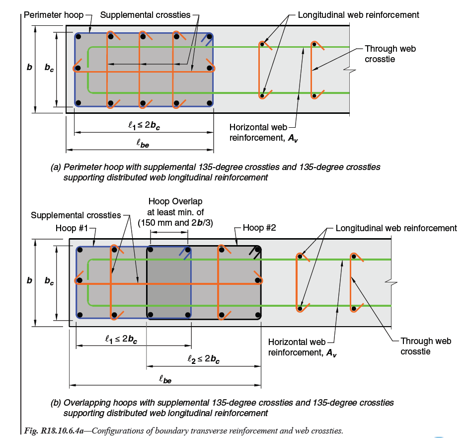
Fig. R18.10.6.4a—Configurations of boundary transverse reinforcement and web crossties. | |
| | |
| American Concrete Institute – Copyrighted © Material – www.concrete.org | |
| PART 5: EARTHQUAKE RESISTANCE 327 | |
| 18 Seismic | |
| No further reproduction or distribution is permitted. | |
| | |
| | |
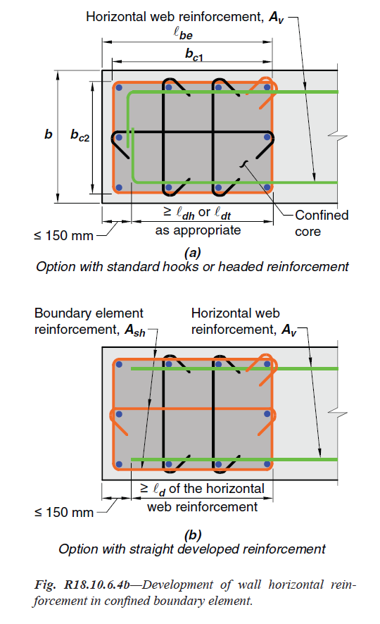
Fig. R18.10.6.4b—Development of wall horizontal reinforcement | |
| in confined boundary element. | |
| | |
| American Concrete Institute – Copyrighted © Material – www.concrete.org | |
| 328 ACI 318-19: BUILDING CODE REQUIREMENTS FOR STRUCTURAL CONCRETE | |
| No further reproduction or distribution is permitted. | |
| | |

Fig. R18.10.6.4c—Summary of boundary element requirements for special walls. | |
| | |
| American Concrete Institute – Copyrighted © Material – www.concrete.org | |
| PART 5: EARTHQUAKE RESISTANCE 329 | |
| 18 Seismic | |
| No further reproduction or distribution is permitted. | |
| | |
=== 18.10.6.5 Where special boundary elements are not required | |
| by 18.10.6.2 or 18.10.6.3, (a) and (b) shall be satisfied: | |
| (a) Except where Vu in the plane of the wall is less than | |
| 0.083λ �.sqrt(fc').Acv, horizontal reinforcement terminating at | |
| the edges of structural walls without boundary elements | |
| shall have a standard hook engaging the edge reinforcement | |
| or the edge reinforcement shall be enclosed in U-stirrups | |
| having the same size and spacing as, and spliced to, | |
| the horizontal reinforcement. | |
| (b) If the maximum longitudinal reinforcement ratio at the | |
| wall boundary exceeds 2.8/fy, boundary transverse reinforcement | |
| shall satisfy 18.7.5.2(a) through (e) over the | |
| distance calculated in accordance with 18.10.6.4(a). The | |
| vertical spacing of transverse reinforcement at the wall | |
| boundary shall be in accordance with Table 18.10.6.5(b) . | |
.png)
Table 18.10.6.5(b)—Maximum vertical spacing of | |
| transverse reinforcement at wall boundary | |
| | |
| | |
=== R18.10.6.5 Cyclic load reversals may lead to buckling | |
| of boundary longitudinal reinforcement even in cases | |
| where the demands on the boundary of the wall do not | |
| require special boundary elements. For walls with moderate | |
| amounts of boundary longitudinal reinforcement, ties are | |
| required to inhibit buckling. The longitudinal reinforcement | |
| ratio is intended to include only the reinforcement at | |
| the wall boundary, as indicated in Fig. R18.10.6.5 . A greater | |
| spacing of ties relative to 18.10.6.4(e) is allowed due to the | |
| lower deformation demands on the walls. Requirements of | |
=== 18.10.6.5 apply over the entire wall height and are summarized | |
| in Fig. R18.10.6.4c for cases where special boundary | |
| elements are required (Moehle et al. 2011). | |
| The addition of hooks or U-stirrups at the ends of horizontal | |
| wall reinforcement provides anchorage so that the | |
| reinforcement will be effective in resisting shear forces. It | |
| will also tend to inhibit the buckling of the vertical edge | |
| reinforcement. In walls with low in-plane shear, the development | |
| of horizontal reinforcement is not necessary. | |
| Limits on spacing of transverse reinforcement are intended | |
| to prevent bar buckling until reversed cyclic strains extend | |
| well into the inelastic range. To achieve similar performance | |
| capability, smaller spacing is required for higher-strength | |
| longitudinal reinforcement. | |
| | |
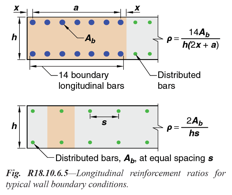
Fig. R18.10.6.5—Longitudinal reinforcement ratios for | |
| typical wall boundary conditions. | |
| | |
== 18.10.7 Coupling beams | |
=== 18.10.7.1 Coupling beams with (ℓn/h) ≥ 4 shall satisfy the | |
| requirements of 18.6, with the wall boundary interpreted as | |
| being a column. The provisions of 18.6.2.1(b) and (c) need | |
| not be satisfied if it can be shown by analysis that the beam | |
| has adequate lateral stability. | |
=== 18.10.7.2 Coupling beams with (ℓn/h) < 2 and with Vu ≥ | |
| 0.33λ.sqrt(fc').Acw shall be reinforced with two intersecting groups | |
| of diagonally placed bars symmetrical about the midspan, | |
| unless it can be shown that loss of stiffness and strength of the | |
| | |
| | |
== R18.10.7 Coupling beams | |
| Coupling beams connecting structural walls can provide | |
| stiffness and energy dissipation. In many cases, geometric | |
| limits result in coupling beams that are deep in relation to | |
| their clear span. Deep coupling beams may be controlled by | |
| shear and may be susceptible to strength and stiffness deterioration | |
| under earthquake loading. Test results (Paulay and | |
| Binney 1974; Barney et al. 1980) have shown that confined | |
| diagonal reinforcement provides adequate resistance in deep | |
| coupling beams. | |
| | |
| American Concrete Institute – Copyrighted © Material – www.concrete.org | |
| 330 ACI 318-19: BUILDING CODE REQUIREMENTS FOR STRUCTURAL CONCRETE | |
| No further reproduction or distribution is permitted. | |
| | |
=== 18.10.7.2 Continuation | |
| coupling beams will not impair the vertical load-carrying ability | |
| of the structure, the egress from the structure, or the integrity of | |
| nonstructural components and their connections to the structure. | |
=== 18.10.7.3 Coupling beams not governed by 18.10.7.1 or | |
=== 18.10.7.2 shall be permitted to be reinforced either with two | |
| intersecting groups of diagonally placed bars symmetrical | |
| about the midspan or according to 18.6.3 through 18.6.5, | |
| with the wall boundary interpreted as being a column. | |
=== 18.10.7.4 Coupling beams reinforced with two intersecting | |
| groups of diagonally placed bars symmetrical about | |
| the midspan shall satisfy (a), (b), and either (c) or (d), and | |
| the requirements of 9.9 need not be satisfied: | |
| (a) Vn shall be calculated by | |
| Vn = 2Avd.fysinα ≤ 0.83.sqrt(fc')Acw (18.10.7.4) | |
| where α is the angle between the diagonal bars and the | |
| longitudinal axis of the coupling beam. | |
| (b) Each group of diagonal bars shall consist of a minimum | |
| of four bars provided in two or more layers. | |
| (c) Each group of diagonal bars shall be enclosed by rectilinear | |
| transverse reinforcement having out-to-out dimensions | |
| of at least bw/2 in the direction parallel to bw and bw/5 | |
| along the other sides, where bw is the web width of the | |
| coupling beam. The transverse reinforcement shall be in | |
| accordance with 18.7.5.2(a) through (e), with Ash not less | |
| than the greater of (i) and (ii): | |
| |
| (i) 0.09 sbc fc'/fy | |
| |
| (ii) 0.3 sbc ( Ag/Ach - 1 ).fc'/fyt | |
| |
| For the purpose of calculating Ag, the concrete cover | |
| in 20.5.1 shall be assumed on all four sides of each | |
| group of diagonal bars. The transverse reinforcement | |
| shall have spacing measured parallel to the diagonal | |
| bars satisfying 18.7.5.3(d) and not exceeding 6db of | |
| the smallest diagonal bars, and shall have spacing of | |
| crossties or legs of hoops measured perpendicular to the | |
| diagonal bars not exceeding 350 mm. The transverse | |
| reinforcement shall continue through the intersection of | |
| the diagonal bars. At the intersection, it is permitted to | |
| modify the arrangement of the transverse reinforcement | |
| provided the spacing and volume ratio requirements are | |
| satisfied. Additional longitudinal and transverse reinforcement | |
| shall be distributed around the beam perimeter | |
| with total area in each direction of at least 0.002bws | |
| and spacing not exceeding 300 mm. | |
| (d) Transverse reinforcement shall be provided for the | |
| entire beam cross section in accordance with 18.7.5.2(a) | |
| through (e) with Ash not less than the greater of (i) and (ii): | |
| | |
== R18.10.7 Continuation | |
| Experiments show that diagonally oriented reinforcement | |
| is effective only if the bars are placed with a large inclination. | |
| Therefore, diagonally reinforced coupling beams are | |
| restricted to beams having aspect ratio ℓn/h < 4. The 2008 | |
| edition of this Code was changed to clarify that coupling | |
| beams of intermediate aspect ratio can be reinforced | |
| according to 18.6.3 through 18.6.5. | |
| Diagonal bars should be placed approximately symmetrically | |
| in the beam cross section, in two or more layers. The | |
| diagonally placed bars are intended to provide the entire | |
| shear and corresponding moment strength of the beam. | |
| Designs deriving their moment strength from combinations | |
| of diagonal and longitudinal bars are not covered by these | |
| provisions. | |
| Two confinement options are described. According to | |
| 18.10.7.4(c), each diagonal element consists of a cage of | |
| longitudinal and transverse reinforcement, as shown in | |
| Fig. R18.10.7a . Each cage contains at least four diagonal | |
| bars and confines a concrete core. The requirement on side | |
| dimensions of the cage and its core is to provide adequate | |
| stability to the cross section when the bars are loaded beyond | |
| yielding. The minimum dimensions and required reinforcement | |
| clearances may control the wall width. Revisions | |
| were made in the 2008 Code to relax spacing of transverse | |
| reinforcement confining the diagonal bars, to clarify that | |
| confinement is required at the intersection of the diagonals, | |
| and to simplify design of the longitudinal and transverse | |
| reinforcement around the beam perimeter; beams with these | |
| new details are expected to perform acceptably. The expressions | |
| for transverse reinforcement Ash are based on ensuring | |
| compression capacity of an equivalent column section is | |
| maintained after spalling of cover concrete. | |
| Section 18.10.7.4(d) describes a second option for | |
| confinement of the diagonals introduced in the 2008 Code | |
| (refer to Fig. R18.10.7b ). This second option is to confine | |
| the entire beam cross section instead of confining the individual | |
| diagonals. This option can considerably simplify field | |
| placement of hoops, which can otherwise be especially challenging | |
| where diagonal bars intersect each other or enter the | |
| wall boundary. | |
| For coupling beams not used as part of the lateral-force-resisting | |
| system, the requirements for diagonal reinforcement | |
| may be waived. | |
| Test results (Barney et al. 1980) demonstrate that beams | |
| reinforced as described in 18.10.7 have adequate ductility | |
| at shear forces exceeding 0.83 � sqrt(fc') bwd. Consequently, the | |
| use of a limit of 0.83 sqrt(fc') Acw provides an acceptable upper | |
| limit. | |
| | |
| American Concrete Institute – Copyrighted © Material – www.concrete.org | |
| PART 5: EARTHQUAKE RESISTANCE 331 | |
| 18 Seismic | |
| No further reproduction or distribution is permitted. | |
| | |
=== 18.10.7.4 Continuation | |
| |
| (i) 0.09 sbc fc'/fyt | |
| |
| (ii) 0.3 sbc (Ag/Ach - 1) fc'/fyt | |
| |
| Longitudinal spacing of transverse reinforcement | |
| shall not exceed the lesser of 150 mm and 6db of the | |
| smallest diagonal bars. Spacing of crossties or legs of | |
| hoops both vertically and horizontally in the plane of | |
| the beam cross section shall not exceed 200 mm. Each | |
| crosstie and each hoop leg shall engage a longitudinal | |
| bar of equal or greater diameter. It shall be permitted to | |
| configure hoops as specified in 18.6.4.3. | |
| | |
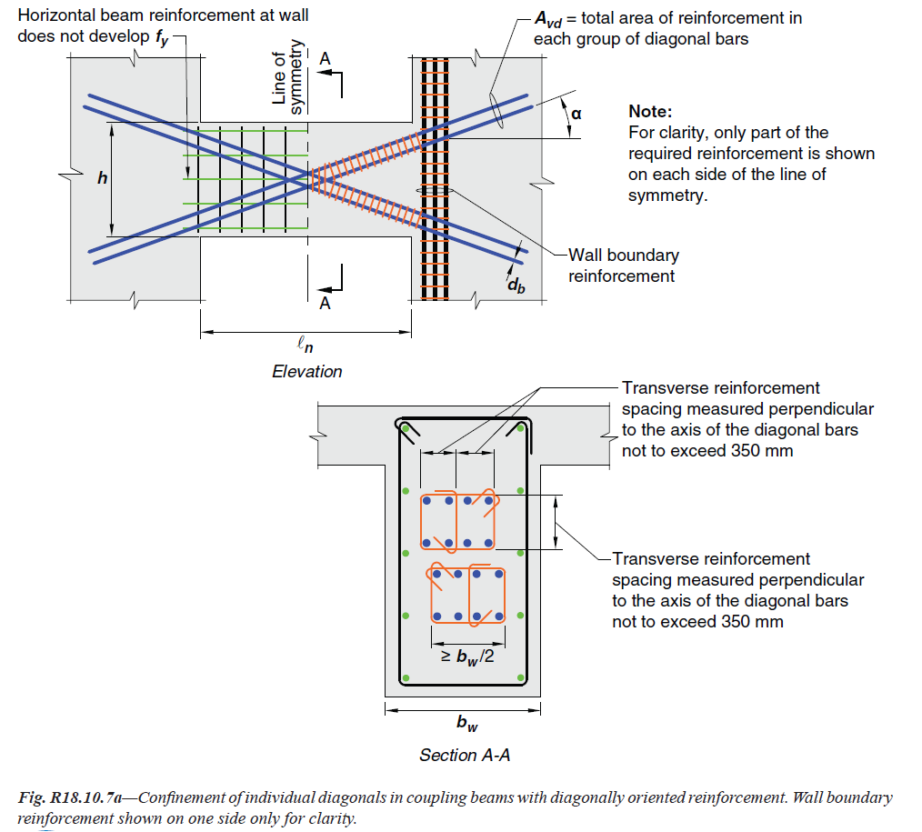
Fig. R18.10.7a—Confinement of individual diagonals in coupling beams with diagonally oriented reinforcement. Wall boundary | |
| reinforcement shown on one side only for clarity. | |
| | |
| American Concrete Institute – Copyrighted © Material – www.concrete.org | |
| 332 ACI 318-19: BUILDING CODE REQUIREMENTS FOR STRUCTURAL CONCRETE | |
| No further reproduction or distribution is permitted. | |
| | |
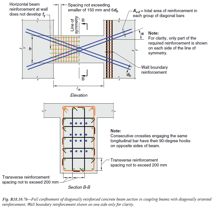
Fig. R18.10.7b—Full confinement of diagonally reinforced concrete beam section in coupling beams with diagonally oriented | |
| reinforcement. Wall boundary reinforcement shown on one side only for clarity. | |
| | |
== 18.10.8 Wall piers | |
=== 18.10.8.1 Wall piers shall satisfy the special moment frame | |
| requirements for columns of 18.7.4, 18.7.5, and 18.7.6, with | |
| joint faces taken as the top and bottom of the clear height of | |
| the wall pier. Alternatively, wall piers with (ℓw/bw) > 2.5 shall | |
| satisfy (a) through (f): | |
| (a) Design shear force shall be calculated in accordance | |
| with 18.7.6.1 with joint faces taken as the top and bottom | |
| of the clear height of the wall pier. If the general building | |
| code includes provisions to account for overstrength of | |
| the seismic-force-resisting system, the design shear force | |
| | |
== R18.10.8 Wall piers | |
| Door and window placements in structural walls sometimes | |
| lead to narrow vertical wall segments that are considered | |
| to be wall piers. The dimensions defining wall piers are | |
| given in Chapter 2. Shear failures of wall piers have been | |
| observed in previous earthquakes. The intent of this section | |
| is to provide sufficient shear strength to wall piers such that | |
| inelastic response, if it occurs, will be primarily in flexure. | |
| The provisions apply to wall piers designated as part of the | |
| seismic-force-resisting system. Provisions for wall piers not | |
| designated as part of the seismic-force-resisting system are | |
| given in 18.14. The effect of all vertical wall segments on the | |
| | |
| | |
| American Concrete Institute – Copyrighted © Material – www.concrete.org | |
| PART 5: EARTHQUAKE RESISTANCE 333 | |
| 18 Seismic | |
| No further reproduction or distribution is permitted. | |
| | |
| | |
== 18.10.8 Continuation | |
| need not exceed Ωo times the factored shear calculated by | |
| analysis of the structure for earthquake load effects. | |
| (b) Vn and distributed shear reinforcement shall satisfy | |
| 18.10.4. | |
| (c) Transverse reinforcement shall be hoops except it shall | |
| be permitted to use single-leg horizontal reinforcement | |
| parallel to ℓw where only one curtain of distributed shear | |
| reinforcement is provided. Single-leg horizontal reinforcement | |
| shall have 180-degree bends at each end that | |
| engage wall pier boundary longitudinal reinforcement. | |
| (d) Vertical spacing of transverse reinforcement shall not | |
| exceed 150 mm_ | |
| (e) Transverse reinforcement shall extend at least 300 mm | |
| above and below the clear height of the wall pier. | |
| (f) Special boundary elements shall be provided if required | |
| by 18.10.6.3. | |
| | |
=== 18.10.8.2 For wall piers at the edge of a wall, horizontal | |
| reinforcement shall be provided in adjacent wall segments | |
| above and below the wall pier and be designed to transfer | |
| the design shear force from the wall pier into the adjacent | |
| wall segments. | |
| | |
== R18.10.8 Continuation | |
| response of the structural system, whether designated as part | |
| of the seismic-force-resisting system or not, should be considered | |
| as required by 18.2.2. Wall piers having (ℓw/bw) ≤ 2.5 | |
| behave essentially as columns. Provision 18.10.8.1 requires | |
| that such members satisfy reinforcement and shear strength | |
| requirements of 18.7.4 through 18.7.6. Alternative provisions | |
| are provided for wall piers having (ℓw/bw) > 2.5. | |
| The design shear force determined according to 18.7.6.1 | |
| may be unrealistically large in some cases. As an alternative, | |
=== 18.10.8.1(a) permits the design shear force to be determined | |
| using factored load combinations in which the earthquake | |
| effect has been amplified to account for system overstrength. | |
| Documents such as the NEHRP provisions (FEMA P749), | |
| ASCE/SEI 7, and the 2018 IBC represent the amplified | |
| earthquake effect using the factor Ωo. | |
| Section 18.10.8.2 addresses wall piers at the edge of a | |
| wall. Under in-plane shear, inclined cracks can propagate | |
| into segments of the wall directly above and below the | |
| wall pier. Unless there is sufficient reinforcement in the | |
| adjacent wall segments, shear failure within the adjacent | |
| wall segments can occur. The length of embedment of the | |
| provided reinforcement into the adjacent wall segments | |
| should be determined considering both development length | |
| requirements and shear strength of the wall segments (refer | |
| to Fig. R18.10.8 ). | |
| | |
| | |
| American Concrete Institute – Copyrighted © Material – www.concrete.org | |
| 334 ACI 318-19: BUILDING CODE REQUIREMENTS FOR STRUCTURAL CONCRETE | |
| No further reproduction or distribution is permitted. | |
| | |
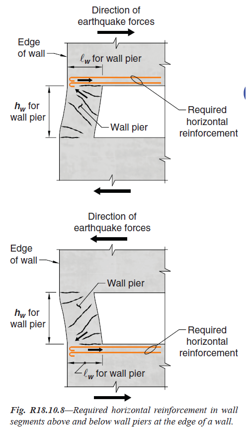
Fig. R18.10.8—Required horizontal reinforcement in wall | |
| segments above and below wall piers at the edge of a wall. | |
| | |
| | |
== 18.10.9 Ductile coupled walls | |
=== 18.10.9.1 Ductile coupled walls shall satisfy the requirements | |
| of this section. | |
=== 18.10.9.2 Individual walls shall satisfy hwcs/ℓw ≥ 2 and the | |
| applicable provisions of 18.10 for special structural walls. | |
=== 18.10.9.3 Coupling beams shall satisfy 18.10.7 and (a) | |
| through (c) in the direction considered. | |
| (a) Coupling beams shall have ℓn/h ≥ 2 at all levels of the | |
| building. | |
| (b) All coupling beams at a floor level shall have ℓn/h ≤ 5 | |
| in at least 90 percent of the levels of the building. | |
| (c) The requirements of 18.10.2.5 shall be satisfied at both | |
| ends of all coupling beams. | |
| | |
== R18.10.9 Ductile coupled walls | |
| The aspect ratio limits and development length requirements | |
| for ductile coupled walls are intended to induce an | |
| energy dissipation mechanism associated with inelastic | |
| deformation reversal of coupling beams. Wall stiffness and | |
| strength at each end of coupling beams should be sufficient | |
| to develop this intended behavior. | |
| | |
| | |
| American Concrete Institute – Copyrighted © Material – www.concrete.org | |
| PART 5: EARTHQUAKE RESISTANCE 335 | |
| 18 Seismic | |
| No further reproduction or distribution is permitted. | |
| | |
== 18.10.10 Construction joints | |
=== 18.10.10.1 Construction joints in structural walls shall be | |
| specified according to 26.5.6, and contact surfaces shall be | |
| roughened consistent with condition (b) of Table 22.9.4.2 . | |
| | |
== 18.10.11 Discontinuous walls | |
=== 18.10.11.1 Columns supporting discontinuous structural | |
| walls shall be reinforced in accordance with 18.7.5.6. | |
| | |
| | |
[ Lanjut Ke 18.11—Special structural walls constructed | |
| using precast concrete ... ] | |
| |
| |
| |