| |
| |
= 18. CHAPTER 18 — EARTHQUAKE-RESISTANT STRUCTURES | |
| | |
= 18.9 — Special moment frames constructed using | |
| precast concrete. | |
== 18.9.1 Scope | |
=== 18.9.1.1 This section shall apply to special moment | |
| frames constructed using precast concrete forming part of | |
| the seismic-force-resisting system. | |
| | |
= R18.9 — Special moment frames constructed using | |
| precast concrete. | |
| The detailing provisions in 18.9.2.1 and 18.9.2.2 are | |
| intended to produce frames that respond to design displacements | |
| essentially like monolithic special moment frames. | |
| Precast frame systems composed of concrete elements | |
| with ductile connections are expected to experience flexural | |
| yielding in connection regions. Reinforcement in ductile | |
| connections can be made continuous by using mechanical | |
| splices or any other technique that provides development | |
| in tension or compression of at least the specified tensile | |
| strength of bars (Yoshioka and Sekine 1991; Kurose et al. | |
| 1991; Restrepo et al. 1995a,b). Requirements for mechanical | |
| splices are in addition to those in 18.2.7 and are intended to | |
| avoid strain concentrations over a short length of reinforcement | |
| adjacent to a splice device. Additional requirements for | |
| shear strength are provided in 18.9.2.1 to prevent sliding on | |
| connection faces. Precast frames composed of elements with | |
| ductile connections may be designed to promote yielding at | |
| locations not adjacent to the joints. Therefore, design shear | |
| Ve, as calculated according to 18.6.5.1 or 18.7.6.1, may not | |
| be conservative. | |
| | |
| American Concrete Institute – Copyrighted © Material – www.concrete.org | |
| 314 ACI 318-19: BUILDING CODE REQUIREMENTS FOR STRUCTURAL CONCRETE | |
| No further reproduction or distribution is permitted. | |
| | |
= R18.9 continuation | |
| Precast concrete frame systems composed of elements | |
| joined using strong connections are intended to experience | |
| flexural yielding outside the connections. Strong connections | |
| include the length of the mechanical splice hardware | |
| as shown in Fig. R18.9.2.2. Capacity-design techniques are | |
| used in 18.9.2.2(c) to ensure the strong connection remains | |
| elastic following formation of plastic hinges. Additional | |
| column requirements are provided to avoid hinging and | |
| strength deterioration of column-to-column connections. | |
| Strain concentrations have been observed to cause brittle | |
| fracture of reinforcing bars at the face of mechanical splices | |
| in laboratory tests of precast beam-column connections | |
| (Palmieri et al. 1996). Locations of strong connections should | |
| be selected carefully or other measures should be taken, such | |
| as debonding of reinforcing bars in highly stressed regions, | |
| to avoid strain concentrations that can result in premature | |
| fracture of reinforcement. | |
| | |
| | |
== 18.9.2 General | |
=== 18.9.2.1 Special moment frames with ductile connections | |
| constructed using precast concrete shall satisfy (a) through (c): | |
| (a) Requirements of 18.6 through 18.8 for special moment | |
| frames constructed with cast-in-place concrete | |
| (b) Vn for connections calculated according to 22.9 shall | |
| be at least 2Ve, where Ve is in accordance with 18.6.5.1 or | |
| 18.7.6.1 | |
| (c) Mechanical splices of beam reinforcement shall be | |
| located not closer than h/2 from the joint face and shall | |
| satisfy 18.2.7 | |
=== 18.9.2.2 Special moment frames with strong connections | |
| constructed using precast concrete shall satisfy (a) through (e): | |
| (a) Requirements of 18.6 through 18.8 for special moment | |
| frames constructed with cast-in-place concrete; | |
| (b) Provision 18.6.2.1(a) shall apply to segments between | |
| locations where flexural yielding is intended to occur due | |
| to design displacements; | |
| (c) Design strength of the strong connection, ϕSn, shall be | |
| at least Se; | |
| (d) Primary longitudinal reinforcement shall be made | |
| continuous across connections and shall be developed | |
| outside both the strong connection and the plastic hinge | |
| region; | |
| (e) For column-to-column connections, ϕSn shall be at | |
| least 1.4Se, ϕMn shall be at least 0.4Mpr for the column | |
| within the story height, and ϕVn shall be at least Ve in | |
| accordance with 18.7.6.1 ; | |
| | |
== R18.9.2 General | |
| | |
| American Concrete Institute – Copyrighted © Material – www.concrete.org | |
| PART 5: EARTHQUAKE RESISTANCE 315 | |
| 18 Seismic | |
| No further reproduction or distribution is permitted. | |
| | |
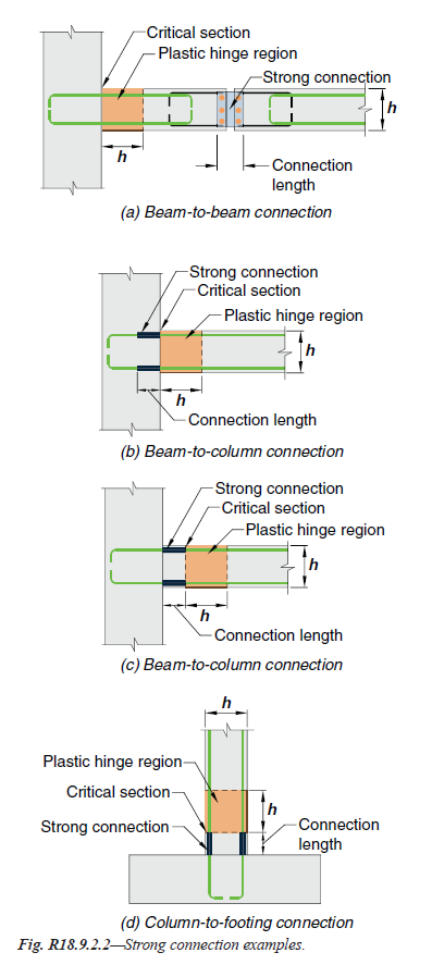
Fig. R18.9.2.2—Strong connection examples. | |
| | |
=== 18.9.2.3 Special moment frames constructed using precast | |
| concrete and not satisfying 18.9.2.1 or 18.9.2.2 shall satisfy | |
| (a) through (c): | |
| |
| (a) ACI 374.1 | |
| (b) Details and materials used in the test specimens shall | |
| be representative of those used in the structure | |
| (c) The design procedure used to proportion the test specimens | |
| shall define the mechanism by which the frame | |
| resists gravity and earthquake effects, and shall establish | |
| acceptance values for sustaining that mechanism. Portions | |
| of the mechanism that deviate from Code requirements | |
| shall be contained in the test specimens and shall be tested | |
| to determine upper bounds for acceptance values. | |
| | |
=== R18.9.2.3 Precast frame systems not satisfying the prescriptive | |
| requirements of Chapter 18 have been demonstrated in | |
| experimental studies to provide satisfactory seismic performance | |
| characteristics (Stone et al. 1995; Nakaki et al. 1995). | |
| | |
| American Concrete Institute – Copyrighted © Material – www.concrete.org | |
| 316 ACI 318-19: BUILDING CODE REQUIREMENTS FOR STRUCTURAL CONCRETE | |
| No further reproduction or distribution is permitted. | |
| | |
=== R18.9.2.3 continuation | |
| ACI 374.1 defines a protocol for establishing a design procedure, | |
| validated by analysis and laboratory tests, for such | |
| frames. The design procedure should identify the load path | |
| or mechanism by which the frame resists gravity and earthquake | |
| effects. The tests should be configured to investigate | |
| critical behaviors, and the measured quantities should establish | |
| upper-bound acceptance values for components of the | |
| load path, which may be in terms of limiting stresses, forces, | |
| strains, or other quantities. The design procedure used for the | |
| structure should not deviate from that used to design the test | |
| specimens, and acceptance values should not exceed values | |
| that were demonstrated by the tests to be acceptable. Materials | |
| and components used in the structure should be similar to those | |
| used in the tests. Deviations may be acceptable if the licensed | |
| design professional can demonstrate that those deviations do | |
| not adversely affect the behavior of the framing system. | |
| ACI 550.3M defines design requirements for one type of | |
| special precast concrete moment frame for use in accordance | |
| with 18.9.2.3. | |
| | |
[ Lanjut Ke 18.10—Special structural walls ... ] | |
| |
| |
| |