| |
| |
= 18. CHAPTER 18 — EARTHQUAKE-RESISTANT STRUCTURES | |
= 18.7 — Columns of special moment frames | |
== 18.7.1 Scope | |
=== 18.7.1.1 This section shall apply to columns of special | |
| moment frames that form part of the seismic-force-resisting | |
| system and are proportioned primarily to resist flexure, | |
| shear, and axial forces. | |
== 18.7.2 Dimensional limits | |
=== 18.7.2.1 Columns shall satisfy (a) and (b): | |
| (a) The shortest cross-sectional dimension, measured on a | |
| straight line passing through the geometric centroid, shall | |
| be at least 300 mm; | |
| (b) The ratio of the shortest cross-sectional dimension to | |
| the perpendicular dimension shall be at least 0.4. | |
| | |
== 18.7.3 Minimum flexural strength of columns | |
| | |
=== 18.7.3.1 Columns shall satisfy 18.7.3.2 or 18.7.3.3, except | |
| at connections where the column is discontinuous above the | |
| connection and the column factored axial compressive force | |
| Pu under load combinations including earthquake effect, E, | |
| are less than Ag fc′/10. | |
| | |
=== 18.7.3.2 The flexural strengths of the columns shall satisfy | |
| ΣMnc ≥ (6/5)ΣMnb (18.7.3.2) | |
| ΣMnc is sum of nominal flexural strengths of columns | |
| framing into the joint, evaluated at the faces of the joint. | |
| Column flexural strength shall be calculated for the factored | |
| axial force, consistent with the direction of the lateral forces | |
| considered, resulting in the lowest flexural strength. | |
| ΣMnb is sum of nominal flexural strengths of the beams | |
| framing into the joint, evaluated at the faces of the joint. | |
| In T-beam construction, where the slab is in tension under | |
| moments at the face of the joint, slab reinforcement within | |
| an effective slab width defined in accordance with 6.3.2 shall | |
| be assumed to contribute to Mnb if the slab reinforcement is | |
| developed at the critical section for flexure. | |
| Flexural strengths shall be summed such that the column | |
| moments oppose the beam moments. Equation (18.7.3.2) | |
| shall be satisfied for beam moments acting in both directions | |
| in the vertical plane of the frame considered. | |
| | |
=== 18.7.3.3 If 18.7.3.2 is not satisfied at a joint, the lateral | |
| strength and stiffness of the columns framing into that joint | |
| shall be ignored when calculating strength and stiffness of | |
| the structure. These columns shall conform to 18.14. | |
| | |
| | |
= R18.7 — Columns of special moment frames | |
== R18.7.1 Scope | |
| This section applies to columns of special moment frames | |
| regardless of the magnitude of axial force. Before 2014, the | |
| Code permitted columns with low levels of axial stress to be | |
| detailed as beams. | |
== R18.7.2 Dimensional limits | |
| The geometric constraints in this provision follow from | |
| previous practice (Seismology Committee of SEAOC 1996). | |
| | |
== R18.7.3 Minimum flexural strength of columns | |
| The intent of 18.7.3.2 is to reduce the likelihood of yielding | |
| in columns that are considered as part of the seismic-forceresisting | |
| system. If columns are not stronger than beams | |
| framing into a joint, there is increased likelihood of inelastic ... | |
| | |
| American Concrete Institute – Copyrighted © Material – www.concrete.org | |
| PART 5: EARTHQUAKE RESISTANCE 305 | |
| 18 Seismic | |
| No further reproduction or distribution is permitted. | |
| | |
== R18.7.3 Continuation | |
| action. In the worst case of weak columns, flexural yielding | |
| can occur at both ends of all columns in a given story, | |
| resulting in a column failure mechanism that can lead to | |
| collapse. Connections with discontinuous columns above the | |
| connection, such as roof-level connections, are exempted if | |
| the column axial load is low, because special moment frame | |
| columns with low axial stress are inherently ductile and | |
| column yielding at such levels is unlikely to create a column | |
| failure mechanism that can lead to collapse. | |
| In 18.7.3.2, the nominal strengths of the beams and | |
| columns are calculated at the joint faces, and those strengths | |
| are compared directly using Eq. (18.7.3.2). The 1995 and | |
| earlier Codes required design strengths to be compared at | |
| the center of the joint, which typically produced similar | |
| results but with added calculation effort. | |
| In determining the nominal moment strength of a beam | |
| section in negative bending (top in tension), longitudinal | |
| reinforcement contained within an effective flange width of a | |
| top slab that acts monolithically with the beam increases the | |
| beam strength. French and Moehle (1991), on beam-column | |
| subassemblies under lateral loading, indicates that using the | |
| effective flange widths defined in 6.3.2 gives reasonable | |
| estimates of beam negative moment strengths of interior | |
| connections at story displacements approaching 2 percent of | |
| story height. This effective width is conservative where the | |
| slab terminates in a weak spandrel. | |
| If 18.7.3.2 cannot be satisfied at a joint, 18.7.3.3 requires | |
| that any positive contribution of the column or columns | |
| involved to the lateral strength and stiffness of the structure | |
| is to be ignored. Negative contributions of the column or | |
| columns should not be ignored. For example, ignoring the | |
| stiffness of the columns ought not to be used as a justification | |
| for reducing the design base shear. If inclusion of those | |
| columns in the analytical model of the building results in an | |
| increase in torsional effects, the increase should be considered | |
| as required by the general building code. Furthermore, | |
| the column must be provided with transverse reinforcement | |
| to increase its resistance to shear and axial forces. | |
| | |
| | |
== 18.7.4 Longitudinal reinforcement | |
=== 18.7.4.1 Area of longitudinal reinforcement, Ast, shall be | |
| at least 0.01Ag and shall not exceed 0.06Ag. | |
=== 18.7.4.2 In columns with circular hoops, there shall be at | |
| least six longitudinal bars. | |
| | |
== R18.7.4 Longitudinal reinforcement | |
| The lower limit of the area of longitudinal reinforcement | |
| is to control time-dependent deformations and to have the | |
| yield moment exceed the cracking moment. The upper limit | |
| of the area reflects concern for reinforcement congestion, | |
| load transfer from floor elements to column (especially in | |
| low-rise construction) and the development of high shear | |
| stresses. | |
| Spalling of the shell concrete, which is likely to occur | |
| near the ends of the column in frames of typical configuration, | |
| makes lap splices in these locations vulnerable. If lap | |
| splices are to be used at all, they should be located near the | |
| midheight where stress reversal is likely to be limited to a | |
| smaller stress range than at locations near the joints. Transverse | |
| reinforcement is required along the lap-splice length ... | |
| | |
| American Concrete Institute – Copyrighted © Material – www.concrete.org | |
| 306 ACI 318-19: BUILDING CODE REQUIREMENTS FOR STRUCTURAL CONCRETE | |
| No further reproduction or distribution is permitted. | |
| | |
== R18.7.4 Continuation | |
| because of the uncertainty in moment distributions along the | |
| height and the need for confinement of lap splices subjected | |
| to stress reversals (Sivakumar et al. 1983). | |
| | |
=== 18.7.4.3 Over column clear height, longitudinal reinforcement | |
| shall be selected such that 1.25ℓd ≤ ℓu/2. | |
| | |
=== R18.7.4.3 Bond splitting failure along longitudinal bars | |
| within the clear column height may occur under earthquake | |
| demands (Ichinose 1995; Sokoli and Ghannoum 2016). | |
| Splitting can be controlled by restricting longitudinal bar | |
| size, increasing the amount of transverse reinforcement, or | |
| increasing concrete strength, all of which reduce the development | |
| length of longitudinal bars (ℓd) over column clear | |
| height (ℓu). Increasing the ratio of column-to-beam moment | |
| strength at joints can reduce the inelastic demands on longitudinal | |
| bars in columns under earthquake demands. | |
| | |
=== 18.7.4.4 Mechanical splices shall conform to 18.2.7 and | |
| welded splices shall conform to 18.2.8. Lap splices shall be | |
| permitted only within the center half of the member length, | |
| shall be designed as tension lap splices, and shall be enclosed | |
| within transverse reinforcement in accordance with 18.7.5.2 | |
| and 18.7.5.3. | |
| | |
== 18.7.5 Transverse reinforcement | |
| | |
=== 18.7.5.1 Transverse reinforcement required in 18.7.5.2 | |
| through 18.7.5.4 shall be provided over a length ℓo from each | |
| joint face and on both sides of any section where flexural | |
| yielding is likely to occur as a result of lateral displacements | |
| beyond the elastic range of behavior. Length ℓo shall be at | |
| least the greatest of (a) through (c): | |
| (a) The depth of the column at the joint face or at the | |
| section where flexural yielding is likely to occur | |
| (b) One-sixth of the clear span of the column | |
| (c) 450 mm | |
| | |
=== 18.7.5.2 Transverse reinforcement shall be in accordance | |
| with (a) through (f): | |
| (a) Transverse reinforcement shall comprise either single | |
| or overlapping spirals, circular hoops, or single or overlapping | |
| rectilinear hoops with or without crossties. | |
| (b) Bends of rectilinear hoops and crossties shall engage | |
| peripheral longitudinal reinforcing bars. | |
| (c) Crossties of the same or smaller bar size as the hoops | |
| shall be permitted, subject to the limitation of 25.7.2.2. | |
| Consecutive crossties shall be alternated end for end along | |
| the longitudinal reinforcement and around the perimeter | |
| of the cross section. | |
| (d) Where rectilinear hoops or crossties are used, they | |
| shall provide lateral support to longitudinal reinforcement | |
| in accordance with 25.7.2.2 and 25.7.2.3. | |
| (e) Reinforcement shall be arranged such that the spacing | |
| hx of longitudinal bars laterally supported by the corner of | |
| a crosstie or hoop leg shall not exceed 350 mm around the | |
| perimeter of the column. | |
| (f) Where Pu > 0.3Ag fc′ or fc′ > 70 MPa in columns with | |
| rectilinear hoops, every longitudinal bar or bundle of bars | |
| around the perimeter of the column core shall have lateral | |
| support provided by the corner of a hoop or by a seismic | |
| hook, and the value of hx shall not exceed 200 mm. Pu | |
| shall be the largest value in compression consistent with | |
| factored load combinations including E. | |
| | |
| | |
== R18.7.5 Transverse reinforcement | |
| This section is concerned with confining the concrete and | |
| providing lateral support to the longitudinal reinforcement. | |
| | |
=== R18.7.5.1 This section stipulates a minimum length over | |
| which to provide closely-spaced transverse reinforcement at | |
| the column ends, where flexural yielding normally occurs. | |
| Research results indicate that the length should be increased | |
| by 50 percent or more in locations, such as the base of a | |
| building, where axial loads and flexural demands may be | |
| especially high (Watson et al. 1994). | |
| | |
=== R18.7.5.2 Sections 18.7.5.2 and 18.7.5.3 provide requirements | |
| for configuration of transverse reinforcement for | |
| columns and joints of special moment frames. Figure | |
=== R18.7.5.2 shows an example of transverse reinforcement | |
| provided by one hoop and three crossties. Crossties with | |
| a 90-degree hook are not as effective as either crossties | |
| with 135-degree hooks or hoops in providing confinement. | |
| For lower values of Pu/Ag fc′ and lower concrete compressive | |
| strengths, crossties with 90-degree hooks are adequate | |
| if the ends are alternated along the length and around the | |
| perimeter of the column. For higher values of Pu/Ag fc′, for | |
| which compression-controlled behavior is expected, and for | |
| higher compressive strengths, for which behavior tends to be | |
| more brittle, the improved confinement provided by having | |
| corners of hoops or seismic hooks supporting all longitu- ... | |
| | |
| American Concrete Institute – Copyrighted © Material – www.concrete.org | |
| PART 5: EARTHQUAKE RESISTANCE 307 | |
| 18 Seismic | |
| No further reproduction or distribution is permitted. | |
| | |
=== R18.7.5.2 Continuation | |
| dinal bars is important to achieving intended performance. | |
| Where these conditions apply, crossties with seismic hooks | |
| at both ends are required. The 200 mm limit on hx is also | |
| intended to improve performance under these critical conditions. | |
| For bundled bars, bends or hooks of hoops and crossties | |
| need to enclose the bundle, and longer extensions on | |
| hooks should be considered. Column axial load Pu should | |
| reflect factored compressive demands from both earthquake | |
| and gravity loads. | |
| In past editions of the Code, the requirements for transverse | |
| reinforcement in columns, walls, beam-column joints, and | |
| diagonally reinforced coupling beams referred to the same | |
| equations. In the 2014 edition of the Code, the equations and | |
| detailing requirements differ among the member types based | |
| on consideration of their loadings, deformations, and performance | |
| requirements. Additionally, hx previously referred to | |
| the distance between legs of hoops or crossties. In the 2014 | |
| edition of the Code, hx refers to the distance between longitudinal | |
| bars supported by those hoops or crossties. | |
| | |
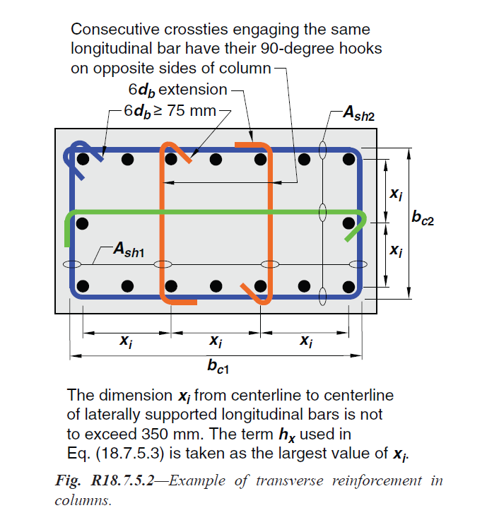
Fig. R18.7.5.2—Example of transverse reinforcement in | |
| columns. | |
| | |
=== 18.7.5.3 Spacing of transverse reinforcement shall not | |
| exceed the least of (a) through (d): | |
| (a) One-fourth of the minimum column dimension | |
| (b) For Grade 420, 6db of the smallest longitudinal bar | |
| (c) For Grade 550, 5db of the smallest longitudinal bar | |
| (d) so, as calculated by: | |
| |
| so = 100 + ( (350-hx)/3 ) | |
| (18.7.5.3) | |
| |
| The value of so from Eq. (18.7.5.3) shall not exceed 150 | |
| mm and need not be taken less than 100 mm. | |
| | |
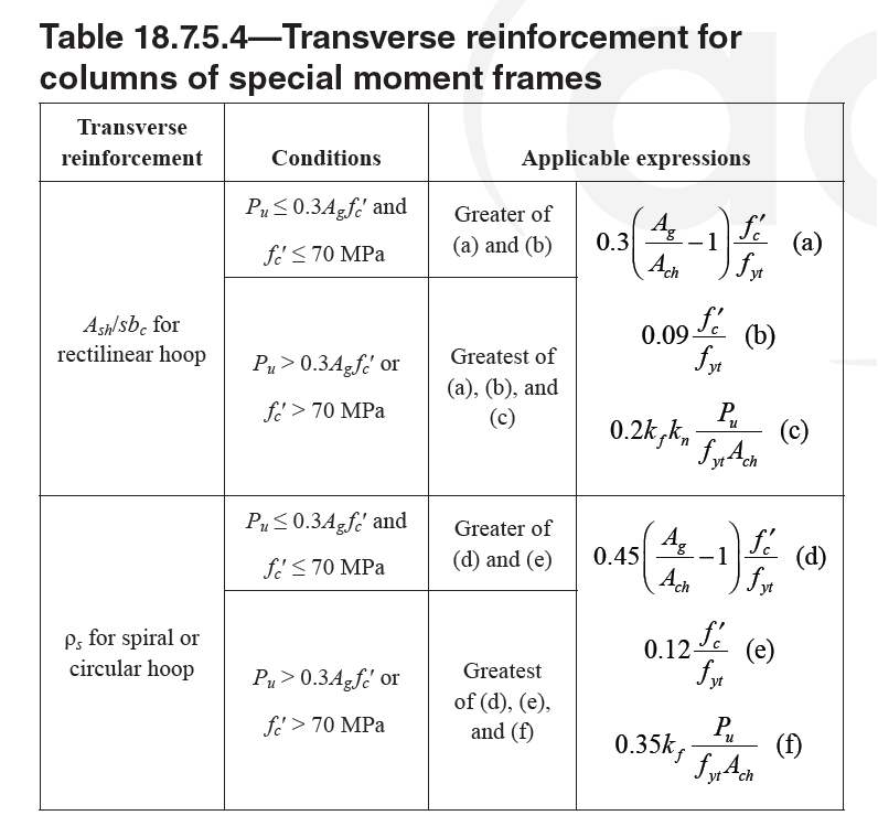
=== 18.7.5.4 Amount of transverse reinforcement shall be in | |
| accordance with Table 18.7.5.4 . | |
| The concrete strength factor kf and confinement effectiveness | |
| factor kn are calculated according to Eq. (18.7.5.4a) and | |
| (18.7.5.4b). | |
| |
| (a) kf = fc'/175 + 0.6 >= 1.0; (18.7.5.4a) | |
| |
| (b) kn = nl / (nl - 2); (18.7.5.4b) | |
| |
| where nl is the number of longitudinal bars or bar bundles | |
| around the perimeter of a column core with rectilinear hoops | |
| that are laterally supported by the corner of hoops or by | |
| seismic hooks. | |

Table 18.7.5.4—Transverse reinforcement for | |
| columns of special moment frames_ | |
| | |
=== R18.7.5.3 The requirement that spacing not exceed onefourth | |
| of the minimum member dimension or 150 mm is for | |
| concrete confinement. If the maximum spacing of crossties or | |
| legs of overlapping hoops within the section is less than 350 | |
| mm, then the 100 mm limit can be increased as permitted by | |
| Eq. (18.7.5.3). The spacing limit as a function of the longitudinal | |
| bar diameter is intended to provide adequate longitudinal | |
| bar restraint to control buckling after spalling. | |
| | |
| American Concrete Institute – Copyrighted © Material – www.concrete.org | |
| 308 ACI 318-19: BUILDING CODE REQUIREMENTS FOR STRUCTURAL CONCRETE | |
| No further reproduction or distribution is permitted. | |
| | |
=== R18.7.5.4 The effect of helical (spiral) reinforcement and | |
| adequately configured rectilinear hoop reinforcement on | |
| deformation capacity of columns is well established (Sakai | |
| and Sheikh 1989). Expressions (a), (b), (d), and (e) in | |
| Table 18.7.5.4 have historically been used in ACI 318 to calculate | |
| the required confinement reinforcement to ensure that | |
| spalling of shell concrete does not result in a loss of column | |
| axial load strength. Expressions (c) and (f) were developed | |
| from a review of column test data (Elwood et al. 2009) and | |
| are intended to result in columns capable of sustaining a drift | |
| ratio of 0.03 with limited strength degradation. Expressions | |
| (c) and (f) are triggered for axial load greater than 0.3Ag fc′, | |
| which corresponds approximately to the onset of compression- | |
| controlled behavior for symmetrically reinforced | |
| columns. The kn term (Paultre and Légeron 2008) decreases | |
| the required confinement for columns with closely spaced, | |
| laterally supported longitudinal reinforcement because such | |
| columns are more effectively confined than columns with | |
| more widely spaced longitudinal reinforcement. The kf term | |
| increases the required confinement for columns with fc′ > 70 | |
| MPa because such columns can experience brittle failure if | |
| not well confined. Concrete strengths greater than 100 MPa | |
| should be used with caution given the limited test data for | |
| such columns. The concrete strength used to determine the | |
| confinement reinforcement is required to be the same as that | |
| specified in the construction documents. | |
| Expressions (a), (b), and (c) in Table 18.7.5.4 are to be | |
| satisfied in both cross-sectional directions of the rectangular | |
| core. For each direction, bc is the core dimension perpendicular | |
| to the tie legs that constitute Ash, as shown in Fig. R18.7.5.2 . | |
| Research results indicate that high strength reinforcement | |
| can be used effectively as confinement reinforcement. | |
| Section 20.2.2.4 permits a value of fyt as high as 690 MPa to | |
| be used in Table 18.7.5.4. | |
| | |
=== 18.7.5.5 Beyond the length ℓo given in 18.7.5.1, the column | |
| shall contain spiral reinforcement satisfying 25.7.3 or hoop | |
| and crosstie reinforcement satisfying 25.7.2 and 25.7.4 with | |
| spacing s not exceeding the least of 150 mm, 6db of the smallest | |
| Grade 420 longitudinal column bar, and 5db of the smallest | |
| Grade 550 longitudinal column bar, unless a greater amount | |
| of transverse reinforcement is required by 18.7.4.4 or 18.7.6. | |
| | |
| | |
| | |
=== R18.7.5.5 This provision is intended to provide reasonable | |
| protection to the midheight of columns outside the length | |
| ℓo. Observations after earthquakes have shown significant | |
| damage to columns in this region, and the minimum hoops | |
| or spirals required should provide more uniform strength of | |
| the column along its length. | |
| | |
| | |
| American Concrete Institute – Copyrighted © Material – www.concrete.org | |
| PART 5: EARTHQUAKE RESISTANCE 309 | |
| 18 Seismic | |
| No further reproduction or distribution is permitted. | |
| | |
=== 18.7.5.6 Columns supporting reactions from discontinued | |
| stiff members, such as walls, shall satisfy (a) and (b): | |
| (a) Transverse reinforcement required by 18.7.5.2 through | |
| 18.7.5.4 shall be provided over the full height at all levels | |
| beneath the discontinuity if the factored axial compressive | |
| force in these columns, related to earthquake effect, | |
| exceeds Ag fc′/10. Where design forces have been magnified | |
| to account for the overstrength of the vertical elements | |
| of the seismic-force-resisting system, the limit of Ag fc′/10 | |
| shall be increased to Ag fc′/4. | |
| (b) Transverse reinforcement shall extend into the discontinued | |
| member at least ℓd of the largest longitudinal | |
| column bar, where ℓd is in accordance with 18.8.5. Where | |
| the lower end of the column terminates on a wall, the | |
| required transverse reinforcement shall extend into the | |
| wall at least ℓd of the largest longitudinal column bar at the | |
| point of termination. Where the column terminates on a | |
| footing or mat, the required transverse reinforcement shall | |
| extend at least 300 mm into the footing or mat. | |
| | |
=== R18.7.5.6 Columns supporting discontinued stiff | |
| members, such as walls or trusses, may develop considerable | |
| inelastic response. Therefore, it is required that these ... | |
| columns have the specified reinforcement throughout their | |
| length. This covers all columns beneath the level at which | |
| the stiff member has been discontinued, unless the factored | |
| forces corresponding to earthquake effect are low. Refer to | |
| R18.12.7.6 for discussion of the overstrength factor Ωo. | |
| | |
=== 18.7.5.7 If the concrete cover outside the confining transverse | |
| reinforcement required by 18.7.5.1, 18.7.5.5, and | |
| 18.7.5.6 exceeds 100 mm, additional transverse reinforcement | |
| having cover not exceeding 100 mm and spacing not | |
| exceeding 300 mm shall be provided. | |
| | |
=== R18.7.5.7 The unreinforced shell may spall as the column | |
| deforms to resist earthquake effects. Separation of portions | |
| of the shell from the core caused by local spalling creates a | |
| falling hazard. The additional reinforcement is required to | |
| reduce the risk of portions of the shell falling away from the | |
| column. | |
| | |
| | |
== 18.7.6 Shear strength | |
=== 18.7.6.1 Design forces | |
==== 18.7.6.1.1 The design shear force Ve shall be calculated | |
| from considering the maximum forces that can be generated | |
| at the faces of the joints at each end of the column. These | |
| joint forces shall be calculated using the maximum probable | |
| flexural strengths, Mpr, at each end of the column associated | |
| with the range of factored axial forces, Pu, acting on the | |
| column. The column shears need not exceed those calculated | |
| from joint strengths based on Mpr of the beams framing into | |
| the joint. In no case shall Ve be less than the factored shear | |
| calculated by analysis of the structure. | |
| | |
=== 18.7.6.2 Transverse reinforcement | |
==== 18.7.6.2.1 Transverse reinforcement over the lengths ℓo, | |
| given in 18.7.5.1, shall be designed to resist shear assuming | |
| Vc = 0 when both (a) and (b) occur: | |
| (a) The earthquake-induced shear force, calculated in | |
| accordance with 18.7.6.1, is at least one-half of the | |
| maximum required shear strength within ℓo. | |
| (b) The factored axial compressive force Pu including | |
| earthquake effects is less than Ag fc′/20. | |
| | |
== R18.7.6 Shear strength | |
=== R18.7.6.1 Design forces | |
==== R18.7.6.1.1 The procedures of 18.6.5.1 also apply to | |
| columns. Above the ground floor, the moment at a joint may | |
| be limited by the flexural strength of the beams framing | |
| into the joint. Where beams frame into opposite sides of | |
| a joint, the combined strength is the sum of the negative | |
| moment strength of the beam on one side of the joint and | |
| the positive moment strength of the beam on the other side | |
| of the joint. Moment strengths are to be determined using a | |
| strength reduction factor of 1.0 and reinforcement with an | |
| effective yield stress equal to at least 1.25fy. Distribution of | |
| the combined moment strength of the beams to the columns | |
| above and below the joint should be based on analysis. | |
| | |
| | |
| American Concrete Institute – Copyrighted © Material – www.concrete.org | |
| 310 ACI 318-19: BUILDING CODE REQUIREMENTS FOR STRUCTURAL CONCRETE | |
| No further reproduction or distribution is permitted. | |
| | |
| | |
[ Lanjut Ke 18.8—Joints of special moment frames ... ] | |
| |
| |
| |