| |
| |
= 18. CHAPTER 18 — EARTHQUAKE-RESISTANT STRUCTURES | |
| | |
= 18.6 — Beams of special moment frames | |
== 18.6.1 Scope | |
| | |
=== 18.6.1.1 This section shall apply to beams of special moment | |
| frames that form part of the seismic-force-resisting system and | |
| are proportioned primarily to resist flexure and shear. | |
=== 18.6.1.2 Beams of special moment frames shall frame into | |
| columns of special moment frames satisfying 18.7. | |
| | |
= R18.6 — Beams of special moment frames | |
== R18.6.1 Scope | |
| This section applies to beams of special moment frames | |
| resisting lateral loads induced by earthquake motions. In | |
| previous Codes, any frame member subjected to a factored | |
| axial compressive force exceeding (Ag fc′/10) under any | |
| load combination was to be proportioned and detailed as | |
| described in 18.7. In the 2014 Code, all requirements for | |
| beams are contained in 18.6 regardless of the magnitude of | |
| axial compressive force. | |
| This Code is written with the assumption that special | |
| moment frames comprise horizontal beams and vertical | |
| columns interconnected by beam-column joints. It is acceptable | |
| for beams and columns to be inclined provided the | |
| resulting system behaves as a frame—that is, lateral resistance | |
| is provided primarily by moment transfer between | |
| beams and columns rather than by strut or brace action. In | |
| special moment frames, it is acceptable to design beams to | |
| resist combined moment and axial force as occurs in beams | |
| that act both as moment frame members and as chords or | |
| collectors of a diaphragm. It is acceptable for beams of | |
| special moment frames to cantilever beyond columns, but | |
| such cantilevers are not part of the special moment frame | |
| that forms part of the seismic-force-resisting system. It is | |
| acceptable for beams of a special moment frame to connect | |
| into a wall boundary if the boundary is reinforced as a | |
| special moment frame column in accordance with 18.7. | |
| A concrete braced frame, in which lateral resistance is | |
| provided primarily by axial forces in beams and columns, is | |
| not a recognized seismic-force-resisting system. | |
| | |
| American Concrete Institute – Copyrighted © Material – www.concrete.org | |
| PART 5: EARTHQUAKE RESISTANCE 299 | |
| 18 Seismic | |
| No further reproduction or distribution is permitted. | |
| | |
== 18.6.2 Dimensional limits | |
=== 18.6.2.1 Beams shall satisfy (a) through (c): | |
| (a) Clear span ℓn shall be at least 4d | |
| (b) Width bw shall be at least the lesser of 0.3h and 250 mm | |
| (c) Projection of the beam width beyond the width of the | |
| supporting column on each side shall not exceed the lesser | |
| of c2 and 0.75c1. | |
| | |
== R18.6.2 Dimensional limits | |
| Experimental evidence (Hirosawa 1977) indicates that, | |
| under reversals of displacement into the nonlinear range, | |
| behavior of continuous members having length-to-depth | |
| ratios of less than 4 is significantly different from the behavior | |
| of relatively slender members. Design rules derived from | |
| experience with relatively slender members do not apply | |
| directly to members with length-to-depth ratios less than 4, | |
| especially with respect to shear strength. | |
| Geometric constraints indicated in 18.6.2.1(b) and (c) were | |
| derived from practice and research (ACI 352R) on reinforced | |
| concrete frames resisting earthquake-induced forces. The limits | |
| in 18.6.2.1(c) define the maximum beam width that can effectively | |
| transfer forces into the beam-column joint. An example | |
| of maximum effective beam width is shown in Fig. R18.6.2. | |
| | |
| | |
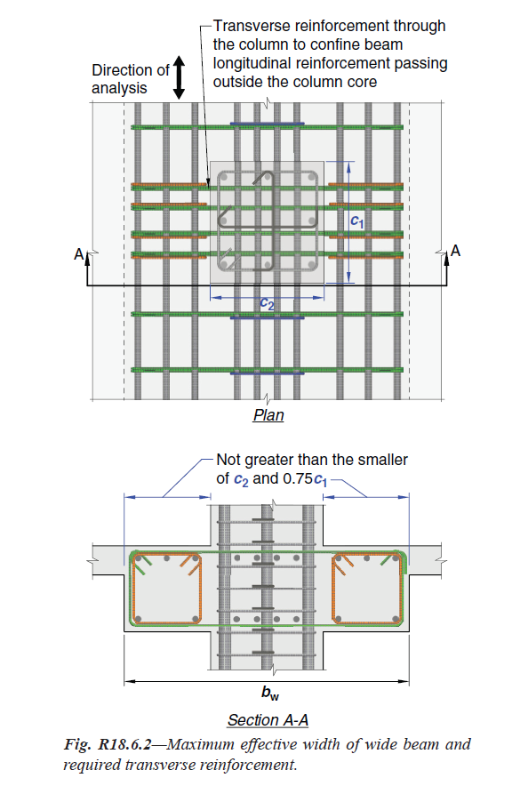
Fig. R18.6.2 — Maximum effective width of wide beam and | |
| required transverse reinforcement. | |
| | |
| | |
| American Concrete Institute – Copyrighted © Material – www.concrete.org | |
| 300 ACI 318-19: BUILDING CODE REQUIREMENTS FOR STRUCTURAL CONCRETE | |
| No further reproduction or distribution is permitted. | |
| | |
== 18.6.3 Longitudinal reinforcement | |
=== 18.6.3.1 Beams shall have at least two continuous bars at | |
| both top and bottom faces. At any section, for top as well as | |
| for bottom reinforcement, the amount of reinforcement shall | |
| be at least that required by 9.6.1.2, and the reinforcement | |
| ratio ρ shall not exceed 0.025 for Grade 420 reinforcement | |
| and 0.02 for Grade 550 reinforcement. | |
=== 18.6.3.2 Positive moment strength at joint face shall be at | |
| least one-half the negative moment strength provided at that | |
| face of the joint. Both the negative and the positive moment | |
| strength at any section along member length shall be at least | |
| one-fourth the maximum moment strength provided at face | |
| of either joint. | |
=== 18.6.3.3 Lap splices of deformed longitudinal reinforcement | |
| shall be permitted if hoop or spiral reinforcement is | |
| provided over the lap length. Spacing of the transverse reinforcement | |
| enclosing the lap-spliced bars shall not exceed the | |
| lesser of d/4 and 100 mm. Lap splices shall not be used in | |
| locations (a) through (c): | |
| (a) Within the joints | |
| (b) Within a distance of twice the beam depth from the | |
| face of the joint; | |
| (c) Within a distance of twice the beam depth from critical | |
| sections where flexural yielding is likely to occur as | |
| a result of lateral displacements beyond the elastic range | |
| of behavior; | |
=== 18.6.3.4 Mechanical splices shall conform to 18.2.7 and | |
| welded splices shall conform to 18.2.8. | |
=== 18.6.3.5 Unless used in a special moment frame as permitted | |
| by 18.9.2.3, prestressing shall satisfy (a) through (d): | |
| (a) The average prestress fpc calculated for an area equal to | |
| the least cross-sectional dimension of the beam multiplied | |
| by the perpendicular cross-sectional dimension shall not | |
| exceed the lesser of 3.5 MPa and fc′/10. | |
| (b) Prestressed reinforcement shall be unbonded in potential | |
| plastic hinge regions, and the calculated strains in | |
| prestressed reinforcement under the design displacement | |
| shall be less than 0.01. | |
| (c) Prestressed reinforcement shall not contribute more | |
| than one-fourth of the positive or negative flexural strength | |
| at the critical section in a plastic hinge region and shall be | |
| anchored at or beyond the exterior face of the joint. | |
| (d) Anchorages of post-tensioning tendons resisting earthquake- | |
| induced forces shall be capable of allowing tendons | |
| to withstand 50 cycles of loading, with prestressed reinforcement | |
| forces bounded by 40 and 85 percent of the | |
| specified tensile strength of the prestressing reinforcement. | |
| | |
| | |
== R18.6.3 Longitudinal reinforcement | |
| | |
=== R18.6.3.1 The limiting reinforcement ratios of 0.025 and | |
| 0.02 are based primarily on considerations of providing | |
| adequate deformation capacity, avoiding reinforcement | |
| congestion, and, indirectly, on limiting shear stresses in | |
| beams of typical proportions. | |
| | |
=== R18.6.3.3 Lap splices of reinforcement are prohibited | |
| along lengths where flexural yielding is anticipated because | |
| such splices are not reliable under conditions of cyclic | |
| loading into the inelastic range. Transverse reinforcement | |
| for lap splices at any location is mandatory because of the | |
| potential of concrete cover spalling and the need to confine | |
| the splice. | |
| | |
=== R18.6.3.5 These provisions were developed, in part, based | |
| on observations of building performance in earthquakes | |
| (ACI 423.3R). For calculating the average prestress, the least | |
| cross-sectional dimension in a beam normally is the web | |
| dimension, and is not intended to refer to the flange thickness. | |
| In a potential plastic hinge region, the limitation on | |
| strain and the requirement for unbonded tendons are intended | |
| to prevent fracture of tendons under inelastic earthquake | |
| deformation. Calculation of strain in the prestressed reinforcement | |
| is required considering the anticipated inelastic | |
| mechanism of the structure. For prestressed reinforcement | |
| unbonded along the full beam span, strains generally will | |
| be well below the specified limit. For prestressed reinforcement | |
| with short unbonded length through or adjacent to the | |
| joint, the additional strain due to earthquake deformation is | |
| calculated as the product of the depth to the neutral axis and | |
| the sum of plastic hinge rotations at the joint, divided by the | |
| unbonded length. | |
| The restrictions on the flexural strength provided by the | |
| tendons are based on the results of analytical and experimental | |
| studies (Ishizuka and Hawkins 1987; Park and | |
| | |
| | |
| | |
| American Concrete Institute – Copyrighted © Material – www.concrete.org | |
| PART 5: EARTHQUAKE RESISTANCE 301 | |
| 18 Seismic | |
| No further reproduction or distribution is permitted. | |
| | |
=== R18.6.3.5 Continuation | |
| Thompson 1977). Although satisfactory seismic performance | |
| can be obtained with greater amounts of prestressed | |
| reinforcement, this restriction is needed to allow the use of | |
| the same response modification and deflection amplification | |
| factors as those specified in model codes for special moment | |
| frames without prestressed reinforcement. Prestressed | |
| special moment frames will generally contain continuous | |
| prestressed reinforcement that is anchored with adequate | |
| cover at or beyond the exterior face of each beam-column | |
| connection located at the ends of the moment frame. | |
| Fatigue testing for 50 cycles of loading between 40 and | |
| 80 percent of the specified tensile strength of the prestressed | |
| reinforcement has been a long-standing industry practice | |
| (ACI 423.3R; ACI 423.7). The 80 percent limit was | |
| increased to 85 percent to correspond to the 1 percent limit | |
| on the strain in prestressed reinforcement. Testing over this | |
| range of stress is intended to conservatively simulate the | |
| effect of a severe earthquake. Additional details on testing | |
| procedures are provided in ACI 423.7. | |
| | |
== 18.6.4 Transverse reinforcement | |
=== 18.6.4.1 Hoops shall be provided in the following regions | |
| of a beam: | |
| (a) Over a length equal to twice the beam depth measured | |
| from the face of the supporting column toward midspan, | |
| at both ends of the beam; | |
| (b) Over lengths equal to twice the beam depth on both | |
| sides of a section where flexural yielding is likely to occur | |
| as a result of lateral displacements beyond the elastic | |
| range of behavior. | |
=== 18.6.4.2 Where hoops are required, primary longitudinal | |
| reinforcing bars closest to the tension and compression faces | |
| shall have lateral support in accordance with 25.7.2.3 and | |
| 25.7.2.4. The spacing of transversely supported flexural | |
| reinforcing bars shall not exceed 350 mm. Skin reinforcement | |
| required by 9.7.2.3 need not be laterally supported. | |
=== 18.6.4.3 Hoops in beams shall be permitted to be made | |
| up of two pieces of reinforcement: a stirrup having seismic | |
| hooks at both ends and closed by a crosstie. Consecutive | |
| crossties engaging the same longitudinal bar shall have their | |
| 90-degree hooks at opposite sides of the flexural member. | |
| If the longitudinal reinforcing bars secured by the crossties | |
| are confined by a slab on only one side of the beam, the | |
| 90-degree hooks of the crossties shall be placed on that side. | |
=== 18.6.4.4 The first hoop shall be located not more than 50 | |
| mm from the face of a supporting column. Spacing of the | |
| hoops shall not exceed the least of (a) through (d): | |
| (a) d/4 | |
| (b) 150 mm | |
| (c) For Grade 420, 6db of the smallest primary flexural | |
| reinforcing bar excluding longitudinal skin reinforcement | |
| required by 9.7.2.3 | |
| (d) For Grade 550, 5db of the smallest primary flexural | |
| reinforcing bar excluding longitudinal skin reinforcement | |
| required by 9.7.2.3 | |
| | |
| | |
== R18.6.4 Transverse reinforcement | |
| Transverse reinforcement is required primarily to confine | |
| the concrete and maintain lateral support for the reinforcing | |
| bars in regions where yielding is expected. Examples of | |
| hoops suitable for beams are shown in Fig. R18.6.4. | |
| In earlier Code editions, the upper limit on hoop spacing | |
| was the least of d/4, eight longitudinal bar diameters, 24 tie | |
| bar diameters, and 300 mm. The upper limits were changed in | |
| the 2011 edition because of concerns about adequacy of longitudinal | |
| bar buckling restraint and confinement in large beams. | |
| In the case of members with varying strength along the | |
| span or members for which the permanent load represents a | |
| large proportion of the total design load, concentrations of | |
| inelastic rotation may occur within the span. If such a condition | |
| is anticipated, transverse reinforcement is also required | |
| in regions where yielding is expected. Because spalling of | |
| the concrete shell might occur, especially at and near regions | |
| of flexural yielding, all web reinforcement is required to be | |
| provided in the form of closed hoops. | |
| | |
| American Concrete Institute – Copyrighted © Material – www.concrete.org | |
| 302 ACI 318-19: BUILDING CODE REQUIREMENTS FOR STRUCTURAL CONCRETE | |
| No further reproduction or distribution is permitted. | |
| | |
=== 18.6.4.5 Where hoops are required, they shall be designed | |
| to resist shear according to 18.6.5. | |
=== 18.6.4.6 Where hoops are not required, stirrups with | |
| seismic hooks at both ends shall be spaced at a distance not | |
| more than d/2 throughout the length of the beam. | |
=== 18.6.4.7 In beams having factored axial compressive | |
| force exceeding Ag fc′/10, hoops satisfying 18.7.5.2 through | |
| 18.7.5.4 shall be provided along lengths given in 18.6.4.1. | |
| Along the remaining length, hoops satisfying 18.7.5.2 shall | |
| have spacing s not exceeding the least of 150 mm, 6db of the | |
| smallest Grade 420 enclosed longitudinal beam bar, and 5db | |
| of the smallest Grade 550 enclosed longitudinal beam bar. | |
| Where concrete cover over transverse reinforcement exceeds | |
| 100 mm, additional transverse reinforcement having cover | |
| not exceeding 100 mm and spacing not exceeding 300 mm | |
| shall be provided. | |
| | |
| | |
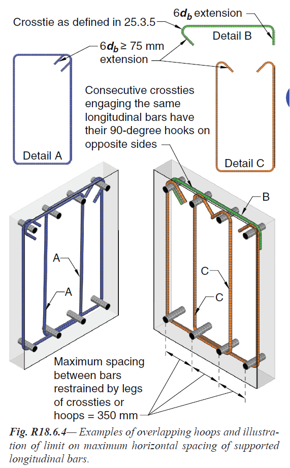
Fig. R18.6.4 — Examples of overlapping hoops and illustration | |
| of limit on maximum horizontal spacing of supported | |
| longitudinal bars. | |
| | |
== 18.6.5 Shear strength | |
=== 18.6.5.1 Design forces | |
| The design shear force Ve shall be calculated from consideration | |
| of the forces on the portion of the beam between faces | |
| of the joints. It shall be assumed that moments of opposite | |
| sign corresponding to probable flexural strength, Mpr, act at | |
| the joint faces and that the beam is loaded with the factored | |
| gravity and vertical earthquake loads along its span. | |
=== 18.6.5.2 Transverse reinforcement | |
| Transverse reinforcement over the lengths identified in | |
| 18.6.4.1 shall be designed to resist shear assuming Vc = 0 | |
| when both (a) and (b) occur: | |
| (a) The earthquake-induced shear force calculated in | |
| accordance with 18.6.5.1 represents at least one-half of | |
| the maximum required shear strength within those lengths. | |
| (b) The factored axial compressive force Pu including | |
| earthquake effects is less than Ag fc′/20. | |
| | |
| | |
== R18.6.5 Shear strength | |
| Unless a beam possesses a moment strength that is on | |
| the order of 3 or 4 times the design moment, it should be | |
| assumed that it will yield in flexure in the event of a major | |
| earthquake. The design shear force should be selected so as | |
| to be a good approximation of the maximum shear that may | |
| develop in a member. Therefore, required shear strength | |
| for frame members is related to flexural strengths of the | |
| designed member rather than to factored shear forces indicated | |
| by lateral load analysis. The conditions described by | |
| 18.6.5.1 are illustrated in Fig. R18.6.5. The figure also shows | |
| that vertical earthquake effects are to be included, as is typically | |
| required by the general building code. For example, | |
| ASCE/SEI 7 requires vertical earthquake effects, 0.2SDS, to | |
| be included. | |
| Because the actual yield strength of the longitudinal | |
| reinforcement may exceed the specified yield strength and | |
| because strain hardening of the reinforcement is likely to | |
| | |
| American Concrete Institute – Copyrighted © Material – www.concrete.org | |
| PART 5: EARTHQUAKE RESISTANCE 303 | |
| 18 Seismic | |
| No further reproduction or distribution is permitted. | |
| | |
== R18.6.5 Continuation | |
| take place at a joint subjected to large rotations, required | |
| shear strengths are determined using a stress of at least | |
| 1.25fy in the longitudinal reinforcement. | |
| Experimental studies (Popov et al. 1972) of reinforced | |
| concrete members subjected to cyclic loading have demonstrated | |
| that more shear reinforcement is required to ensure | |
| a flexural failure if the member is subjected to alternating | |
| nonlinear displacements than if the member is loaded in only | |
| one direction: the necessary increase of shear reinforcement | |
| being higher in the case of no axial load. This observation | |
| is reflected in the Code (refer to 18.6.5.2) by eliminating | |
| the term representing the contribution of concrete to shear | |
| strength. The added conservatism on shear is deemed necessary | |
| in locations where potential flexural hinging may occur. | |
| However, this stratagem, chosen for its relative simplicity, | |
| should not be interpreted to mean that no concrete is | |
| required to resist shear. On the contrary, it may be argued | |
| that the concrete core resists all the shear with the shear | |
| (transverse) reinforcement confining and strengthening the | |
| concrete. The confined concrete core plays an important | |
| role in the behavior of the beam and should not be reduced | |
| to a minimum just because the design expression does not | |
| explicitly recognize it. | |
| | |
| | |
| American Concrete Institute – Copyrighted © Material – www.concrete.org | |
| 304 ACI 318-19: BUILDING CODE REQUIREMENTS FOR STRUCTURAL CONCRETE | |
| No further reproduction or distribution is permitted. | |
| | |
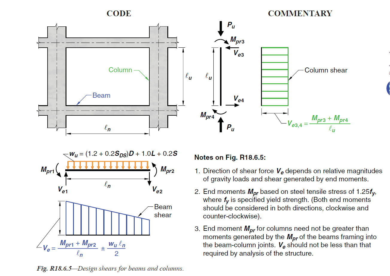
Fig. R18.6.5 — Design shears for beams and columns. | |
| | |
| American Concrete Institute – Copyrighted © Material – www.concrete.org | |
| PART 5: EARTHQUAKE RESISTANCE 305 | |
| 18 Seismic | |
| No further reproduction or distribution is permitted. | |
| | |
| | |
[ Lanjut Ke 18.7—Columns of special moment frames ... ] | |
| |
| |
| |