| |
| |
= 18. CHAPTER 18 — EARTHQUAKE-RESISTANT STRUCTURES | |
= 18.2 — General | |
== 18.2.1 Structural systems | |
=== 18.2.1.1 All structures shall be assigned to a SDC in accordance | |
| with 4.4.6.1. | |
| | |
= R18.2 — General | |
| Structures assigned to SDC A need not satisfy requirements | |
| of Chapter 18 but must satisfy all other applicable | |
| requirements of this Code. Structures assigned to Seismic | |
| Design Categories B through F must satisfy requirements of | |
| | |
| American Concrete Institute – Copyrighted © Material – www.concrete.org | |
| PART 5: EARTHQUAKE RESISTANCE 285 | |
| 18 Seismic | |
| CHAPTER 18—EARTHQUAKE-RESISTANT STRUCTURES | |
| No further reproduction or distribution is permitted. | |
| | |
COMMENTARY | |
| Chapter 18 in addition to all other applicable requirements | |
| of this Code. | |
| Sections 18.2.1.3 through 18.2.1.5 identify those parts of | |
| Chapter 18 that apply to the building based on its assigned | |
| SDC, regardless of the vertical elements of the seismic-force- | |
| resisting system. ASCE/SEI 7 defines the permissible | |
| vertical elements of the seismic-force-resisting system and | |
| applies where adopted. The remaining commentary of R18.2 | |
| summarizes the intent of ACI 318 regarding which vertical | |
| elements should be permissible in a building considering | |
| its SDC. Section 18.2.1.6 defines the requirements for the | |
| vertical elements of the seismic-force-resisting system. | |
| The design and detailing requirements should be compatible | |
| with the level of inelastic response assumed in the calculation | |
| of the design earthquake forces. The terms “ordinary,” | |
| “intermediate,” and “special” are used to facilitate this | |
| compatibility. For any given structural element or system, | |
| the terms “ordinary,” “intermediate,” and “special,” refer | |
| to increasing requirements for detailing and proportioning, | |
| with expectations of increased deformation capacity. Structures | |
| assigned to SDC B are not expected to be subjected | |
| to strong ground motion, but instead are expected to experience | |
| low levels of ground motion at long time intervals. | |
| This Code provides some requirements for beam-column | |
| ordinary moment frames to improve deformation capacity. | |
| Structures assigned to SDC C may be subjected to moderately | |
| strong ground motion. The designated seismic-force-resisting | |
| system typically comprises some combination of | |
| ordinary cast-in-place structural walls, intermediate precast | |
| structural walls, and intermediate moment frames. The | |
| general building code also may contain provisions for use | |
| of other seismic-force-resisting systems in SDC C. Provision | |
| 18.2.1.6 defines requirements for whatever system is | |
| selected. | |
| Structures assigned to SDC D, E, or F may be subjected to | |
| strong ground motion. It is the intent of ACI Committee 318 | |
| that the seismic-force-resisting system of structural concrete | |
| buildings assigned to SDC D, E, or F be provided by special | |
| moment frames, special structural walls, or a combination | |
| of the two. In addition to 18.2.2 through 18.2.8, these structures | |
| also are required to satisfy requirements for continuous | |
| inspection (26.13.1.3), diaphragms and trusses (18.12), foundations | |
| (18.13), and gravity-load-resisting elements that are | |
| not designated as part of the seismic-force-resisting system | |
| (18.14). These provisions have been developed to provide | |
| the structure with adequate deformation capacity for the | |
| high demands expected for these seismic design categories. | |
| The general building code may also permit the use of intermediate | |
| moment frames as part of dual systems for some | |
| buildings assigned to SDC D, E, or F. It is not the intent | |
| of ACI Committee 318 to recommend the use of intermediate | |
| moment frames as part of moment-resisting frame or | |
| dual systems in SDC D, E, or F. The general building code | |
| may also permit substantiated alternative or nonprescriptive | |
| designs or, with various supplementary provisions, the use | |
| | |
=== 18.2.1.2 All members shall satisfy Chapters 1 to 17 and | |
| 19 to 26. Structures assigned to SDC B, C, D, E, or F also | |
| shall satisfy 18.2.1.3 through 18.2.1.7, as applicable. Where | |
| Chapter 18 conflicts with other chapters of this Code, | |
| Chapter 18 shall govern. | |
=== 18.2.1.3 Structures assigned to SDC B shall satisfy 18.2.2 . | |
=== 18.2.1.4 Structures assigned to SDC C shall satisfy 18.2.2, | |
| 18.2.3, and 18.13. | |
=== 18.2.1.5 Structures assigned to SDC D, E, or F shall satisfy | |
| 18.2.2 through 18.2.8 and 18.12 through 18.14. | |
=== 18.2.1.6 Structural systems designated as part of the | |
| seismic-force-resisting system shall be restricted to those | |
| designated by the general building code, or determined by | |
| other authority having jurisdiction in areas without a legally | |
| adopted building code. Except for SDC A, for which Chapter | |
| 18 does not apply, (a) through (h) shall be satisfied for each | |
| structural system designated as part of the seismic-forceresisting | |
| system, in addition to 18.2.1.3 through 18.2.1.5: | |
| |
| (a) Ordinary moment frames shall satisfy 18.3 | |
| (b) Ordinary reinforced concrete structural walls need | |
| not satisfy any detailing provisions in Chapter 18, unless | |
| required by 18.2.1.3 or 18.2.1.4 | |
| (c) Intermediate moment frames shall satisfy 18.4 | |
| (d) Intermediate precast walls shall satisfy 18.5 | |
| (e) Special moment frames shall satisfy 18.2.3 through | |
| 18.2.8 and 18.6 through 18.8 | |
| (f) Special moment frames constructed using precast | |
| concrete shall satisfy 18.2.3 through 18.2.8 and 18.9 | |
| (g) Special structural walls shall satisfy 18.2.3 through | |
| 18.2.8 and 18.10 | |
| (h) Special structural walls constructed using precast | |
| concrete shall satisfy 18.2.3 through 18.2.8 and 18.11 | |
| |
=== 18.2.1.7 A reinforced concrete structural system not satisfying | |
| this chapter shall be permitted if it is demonstrated by | |
| experimental evidence and analysis that the proposed system | |
| will have strength and toughness equal to or exceeding those | |
| provided by a comparable reinforced concrete structure | |
| satisfying this chapter. | |
| | |
| American Concrete Institute – Copyrighted © Material – www.concrete.org | |
| 286 ACI 318-19: BUILDING CODE REQUIREMENTS FOR STRUCTURAL CONCRETE | |
| No further reproduction or distribution is permitted. | |
| | |
COMMENTARY | |
| of ordinary or intermediate systems for nonbuilding structures | |
| in the higher seismic design categories. These are not | |
| the typical applications that were considered in the writing | |
| of this chapter, but wherever the term “ordinary or intermediate | |
| moment frame” is used in reference to reinforced | |
| concrete, 18.3 or 18.4 apply. | |
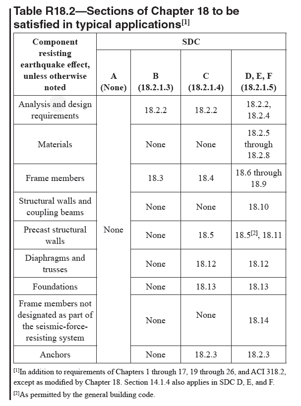
| Table 18.2 summarizes the applicability of the provisions | |
| of Chapter 18 as they are typically applied when using | |
| the minimum requirements in the various seismic design | |
| categories. Where special systems are used for structures in | |
| SDC B or C, it is not required to satisfy the requirements | |
| of 18.14, although it should be verified that members not | |
| designated as part of the seismic-force-resisting system will | |
| be stable under design displacements. | |
| |

Table R18.2 — Sections of Chapter 18 to be | |
| satisfied in typical applications[1] | |
| |
| The proportioning and detailing requirements in Chapter | |
| 18 are based predominantly on field and laboratory experience | |
| with monolithic reinforced concrete building structures | |
| and precast concrete building structures designed | |
| and detailed to behave like monolithic building structures. | |
| Extrapolation of these requirements to other types of castin- | |
| place or precast concrete structures should be based on | |
| evidence provided by field experience, tests, or analysis. The | |
| acceptance criteria for moment frames given in ACI 374.1 can | |
| be used in conjunction with Chapter 18 to demonstrate that the | |
| | |
| American Concrete Institute – Copyrighted © Material – www.concrete.org | |
| PART 5: EARTHQUAKE RESISTANCE 287 | |
| 18 Seismic | |
| No further reproduction or distribution is permitted. | |
| | |
COMMENTARY | |
| strength, energy dissipation capacity, and deformation capacity | |
| of a proposed frame system equals or exceeds that provided | |
| by a comparable monolithic concrete system. ACI ITG-5.1M | |
| provides similar information for precast wall systems. | |
| The toughness requirement in 18.2.1.7 refers to the | |
| requirement to maintain structural integrity of the entire | |
| seismic-force-resisting system at lateral displacements | |
| anticipated for the maximum considered earthquake motion. | |
| Depending on the energy-dissipation characteristics of the | |
| structural system used, such displacements may be larger | |
| than for a monolithic reinforced concrete structure satisfying | |
| the prescriptive provisions of other parts of this Code. | |
| | |
CODE | |
== 18.2.2 Analysis and proportioning of structural members | |
=== 18.2.2.1 The interaction of all structural and nonstructural | |
| members that affect the linear and nonlinear response of the | |
| structure to earthquake motions shall be considered in the | |
| analysis. | |
=== 18.2.2.2 Rigid members assumed not to be a part of the | |
| seismic-force-resisting system shall be permitted provided | |
| their effect on the response of the system is considered in | |
| the structural design. Consequences of failure of structural | |
| and nonstructural members that are not a part of the seismicforce- | |
| resisting system shall be considered. | |
=== 18.2.2.3 Structural members extending below the base of | |
| structure that are required to transmit forces resulting from | |
| earthquake effects to the foundation shall comply with the | |
| requirements of Chapter 18 that are consistent with the | |
| seismic-force-resisting system above the base of structure. | |
| | |
== R18.2.2 Analysis and proportioning of structural members | |
| It is assumed that the distribution of required strength to the | |
| various components of a seismic-force-resisting system will | |
| be determined from the analysis of a linearly elastic model of | |
| the system acted upon by the factored forces, as required by | |
| the general building code. If nonlinear response history analyses | |
| are to be used, base motions should be selected after a | |
| detailed study of the site conditions and local seismic history. | |
| Because the basis for earthquake-resistant design admits | |
| nonlinear response, it is necessary to investigate the stability of | |
| the seismic-force-resisting system, as well as its interaction with | |
| other structural and nonstructural members, under expected | |
| lateral displacements corresponding to maximum considered | |
| earthquake ground motion. For lateral displacement calculations, | |
| assuming all the structural members to be fully cracked is | |
| likely to lead to better estimates of the possible drift than using | |
| uncracked stiffness for all members. The analysis assumptions | |
| described in 6.6.3.1 may be used to estimate lateral deflections | |
| of reinforced concrete building systems. | |
| The main objective of Chapter 18 is the safety of the structure. | |
| The intent of 18.2.2.1 and 18.2.2.2 is to draw attention | |
| to the influence of nonstructural members on structural | |
| response and to hazards from falling objects. | |
| Section 18.2.2.3 serves as an alert that the base of structure as | |
| defined in analysis may not necessarily correspond to the foundation | |
| or ground level. Details of columns and walls extending | |
| below the base of structure to the foundation are required to be | |
| consistent with those above the base of structure. | |
| In selecting member sizes for earthquake-resistant structures, | |
| it is important to consider constructibility problems | |
| related to congestion of reinforcement. The design should | |
| be such that all reinforcement can be assembled and placed | |
| in the proper location and that concrete can be cast and | |
| consolidated properly. Using the upper limits of permitted | |
| reinforcement ratios may lead to construction problems. | |
| | |
| | |
| | |
== 18.2.3 Anchoring to concrete | |
=== 18.2.3.1 Anchors resisting earthquake-induced forces in | |
| structures assigned to SDC C, D, E, or F shall be in accordance | |
| with 17.10. | |
| | |
| American Concrete Institute – Copyrighted © Material – www.concrete.org | |
| 288 ACI 318-19: BUILDING CODE REQUIREMENTS FOR STRUCTURAL CONCRETE | |
| No further reproduction or distribution is permitted. | |
| | |
== 18.2.4 Strength reduction factors | |
=== 18.2.4.1 Strength reduction factors shall be in accordance | |
| with Chapter 21. | |
| | |
== R18.2.4 Strength reduction factors | |
=== R18.2.4.1 Chapter 21 contains strength reduction factors | |
| for all members, joints, and connections of earthquake-resistant | |
| structures, including specific provisions in 21.2.4 for | |
| buildings that use special moment frames, special structural | |
| walls, and intermediate precast walls. | |
| | |
== 18.2.5 Concrete in special moment frames and special | |
| structural walls | |
=== 18.2.5.1 Specified compressive strength of concrete in | |
| special moment frames and special structural walls shall be | |
| in accordance with the special seismic systems requirements | |
| of Table 9.2.1.1 . | |
== R18.2.5 Concrete in special moment frames and special | |
| structural walls | |
| Requirements of this section refer to concrete quality in | |
| frames and walls that resist earthquake-induced forces. The | |
| maximum specified compressive strength of lightweight | |
| concrete to be used in structural design calculations is limited | |
| to 35 MPa, primarily because of paucity of experimental and | |
| field data on the behavior of members made with lightweight | |
| concrete subjected to displacement reversals in the nonlinear | |
| range. If convincing evidence is developed for a specific | |
| application, the limit on maximum specified compressive | |
| strength of lightweight concrete may be increased to a level | |
| justified by the evidence. | |
| | |
== 18.2.6 Reinforcement in special moment frames and | |
| special structural walls | |
=== 18.2.6.1 Reinforcement in special moment frames and | |
| special structural walls shall be in accordance with the | |
| special seismic systems requirements of 20.2.2. | |
| | |
== R18.2.6 Reinforcement in special moment frames and | |
| special structural walls | |
=== R18.2.6.1 Nonprestressed reinforcement for seismic | |
| systems is required to meet 20.2.2.4 and 20.2.2.5. Starting | |
| with ACI 318-19, ASTM A706 Grades 550 and 690 reinforcement | |
| is permitted to resist moments, axial, and shear | |
| forces in special structural walls and all components of | |
| special structural walls, including coupling beams and | |
| wall piers. ASTM A706 Grade 550 reinforcement is also | |
| permitted in special moment frames. Results of tests and | |
| analytical studies presented in NIST (2014) and Sokoli and | |
| Ghannoum (2016) indicate that properly detailed beams and | |
| columns of special moment frames with ASTM A706 Grade | |
| 550 reinforcement exhibit strength and deformation capacities | |
| similar to those of members reinforced with Grade 420 | |
| reinforcement. The use of Grade 690 reinforcement is not | |
| allowed in special moment frames because there is insufficient | |
| data to demonstrate satisfactory seismic performance. | |
| To allow the use of ASTM A706 Grades 550 and 690 | |
| reinforcement, the 2019 Code includes limits for spacing of | |
| transverse reinforcement to provide adequate longitudinal | |
| bar support to control longitudinal bar buckling. In special | |
| moment frames, the use of Grade 550 reinforcement requires | |
| increased joint depths to prevent excessive slip of beam bars | |
| passing through beam-column joints (18.8.2.3). | |
| The requirement for a tensile strength greater than the yield | |
| strength of the reinforcement ( 20.2.2.5 , Table 0.2.1.3 (b)) is | |
| based on the assumption that the capability of a structural | |
| member to develop inelastic rotation capacity is a function | |
| of the length of the yield region along the axis of the | |
| member. In interpreting experimental results, the length of | |
| | |
| American Concrete Institute – Copyrighted © Material – www.concrete.org | |
| PART 5: EARTHQUAKE RESISTANCE 289 | |
| 18 Seismic | |
| No further reproduction or distribution is permitted. | |
| | |
COMMENTARY | |
| the yield region has been related to the relative magnitudes | |
| of nominal and yield moments (ACI 352R). According to | |
| this interpretation, the greater the ratio of nominal to yield | |
| moment, the longer the yield region. Chapter 20 requires | |
| that the ratio of actual tensile strength to actual yield strength | |
| be at least 1.25 for ASTM A615 Grade 420. | |
| The restrictions on the value of fyt apply to all types of | |
| transverse reinforcement, including spirals, circular hoops, | |
| rectilinear hoops, and crossties. Research results (Budek | |
| et al. 2002; Muguruma and Watanabe 1990; Sugano et al. | |
| 1990) indicate that higher yield strengths can be used effectively | |
| as confinement reinforcement as specified in 18.7.5.4. | |
| The increases to 550 and 690 MPa for shear design of some | |
| special seismic system members is based on research indicating | |
| the design shear strength can be developed (Wallace | |
| 1998; Aoyama 2001; Budek et al. 2002; Sokoli and Ghannoum | |
| 2016; Cheng et al. 2016; Huq et al. 2018; Weber- | |
| Kamin et al. 2019). The 420 MPa restriction on the value of | |
| fyt for deformed bar in 20.2.2.4 for calculating nominal shear | |
| strength is intended to limit the width of shear cracks at | |
| service-level loads. Service-level cracking is not a concern | |
| in members of the seismic-force-resisting system subjected | |
| to design-level earthquake forces. | |
| | |
CODE | |
== 18.2.7 Mechanical splices in special moment frames and | |
| special structural walls | |
| | |
== R18.2.7 Mechanical splices in special moment frames and | |
| special structural walls | |
| In a structure undergoing inelastic deformations during | |
| an earthquake, the tensile stresses in reinforcement may | |
| approach the tensile strength of the reinforcement. The | |
| requirements for Type 2 mechanical splices are intended to | |
| avoid a splice failure when the reinforcement is subjected to | |
| expected stress levels in yielding regions. Type 1 mechanical | |
| splices on any grade of reinforcement and Type 2 mechanical | |
| splices on Grade 550 and Grade 690 reinforcement | |
| may not be capable of resisting the stress levels expected in | |
| yielding regions. The locations of these mechanical splices | |
| are restricted because tensile stresses in reinforcement in | |
| yielding regions can exceed the strength requirements of | |
| 18.2.7.1. The restriction on all Type 1 mechanical splices | |
| and on Type 2 mechanical splices on Grade 550 and Grade | |
| 690 reinforcement applies to all reinforcement resisting | |
| earthquake effects, including transverse reinforcement. | |
| Recommended detailing practice would preclude the | |
| use of splices in regions of potential yielding in members | |
| resisting earthquake effects. If use of mechanical splices in | |
| regions of potential yielding cannot be avoided, there should | |
| be documentation on the actual strength characteristics of the | |
| bars to be spliced, on the force-deformation characteristics | |
| of the spliced bar, and on the ability of the mechanical splice | |
| to be used to meet the specified performance requirements. | |
| Although mechanical splices as defined by 18.2.7 need not | |
| be staggered, staggering is encouraged and may be necessary | |
| for constructibility or provide enough space around the splice | |
| for installation or to meet the clear spacing requirements. | |
| | |
| American Concrete Institute – Copyrighted © Material – www.concrete.org | |
| 290 ACI 318-19: BUILDING CODE REQUIREMENTS FOR STRUCTURAL CONCRETE | |
| No further reproduction or distribution is permitted. | |
| | |
=== 18.2.7.1 Mechanical splices shall be classified as (a) or (b): | |
| (a) Type 1 – Mechanical splice conforming to 25.5.7 | |
| (b) Type 2 – Mechanical splice conforming to 25.5.7 and | |
| capable of developing the specified tensile strength of the | |
| spliced bars | |
=== 18.2.7.2 Except for Type 2 mechanical splices on Grade | |
| 420 reinforcement, mechanical splices shall not be located | |
| within a distance equal to twice the member depth from the | |
| column or beam face for special moment frames or from | |
| critical sections where yielding of the reinforcement is likely | |
| to occur as a result of lateral displacements beyond the linear | |
| range of behavior. Type 2 mechanical splices on Grade 420 | |
| reinforcement shall be permitted at any location, except as | |
| noted in 18.9.2.1(c). | |
| | |
== 18.2.8 Welded splices in special moment frames and | |
| special structural walls | |
=== 18.2.8.1 Welded splices in reinforcement resisting earthquake- | |
| induced forces shall conform to 25.5.7 and shall not | |
| be located within a distance equal to twice the member depth | |
| from the column or beam face for special moment frames or | |
| from critical sections where yielding of the reinforcement is | |
| likely to occur as a result of lateral displacements beyond the | |
| linear range of behavior. | |
=== 18.2.8.2 Welding of stirrups, ties, inserts, or other similar | |
| elements to longitudinal reinforcement required by design | |
| shall not be permitted. | |
| | |
== R18.2.8 Welded splices in special moment frames and | |
| special structural walls | |
=== R18.2.8.1 Welding of reinforcement should be in accordance | |
| with AWS D1.4 as required in Chapter 26. The locations | |
| of welded splices are restricted because reinforcement | |
| tension stresses in yielding regions can exceed the strength | |
| requirements of 25.5.7. The restriction on welded splices | |
| applies to all reinforcement resisting earthquake effects, | |
| including transverse reinforcement. | |
=== R18.2.8.2 Welding of crossing reinforcing bars can lead | |
| to local embrittlement of the steel. If welding of crossing | |
| bars is used to facilitate fabrication or placement of reinforcement, | |
| it should be done only on bars added for such | |
| purposes. The prohibition of welding crossing reinforcing | |
| bars does not apply to bars that are welded with welding | |
| operations under continuous, competent control, as in the | |
| manufacture of welded-wire reinforcement. | |
| | |
[ Lanjut Ke 18.3—Ordinary moment frames ... ] | |
| |
| |
| |