= 6.3 — Modeling assumptions
== 6.3.1 General
=== 6.3.1.1 Relative stiffnesses of members within structural systems shall be selected based on a reasonable set of assumptions. The assumptions shall be consistent throughout each analysis.
=== 6.3.1.2 To calculate moments and shears caused by gravity loads in columns, beams, and slabs, it shall be permitted to use a model limited to the members in the level being considered and the columns above and below that level. It shall be permitted to assume far ends of columns built integrally with the structure to be fixed.
=== 6.3.1.3 The analysis model shall consider the effects of variation of member cross-sectional properties, such as that due to haunches.
= R6.3 — Modeling assumptions
== R6.3.1 General
=== R6.3.1.1 Separate analyses with different stiffness assumptions may be performed for different objectives such as to check serviceability and strength criteria or to bound the demands on elements where stiffness assumptions are critical.
=== R6.3.1.3 Stiffness and fixed-end moment coefficients for haunched members may be obtained from the Portland Cement Association (1972).
== 6.3.2 T-beam geometry
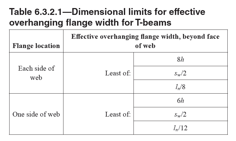
=== 6.3.2.1 For nonprestressed T-beams supporting monolithic or composite slabs, the effective flange width bf shall include the beam web width bw plus an effective overhanging
== R6.3.2 T-beam geometry
=== R6.3.2.1 In ACI 318M-11, the width of the slab effective as a T-beam flange was limited to one-fourth the span. The Code now allows one-eighth of the span on each side of the beam web. This

Table 6.3.2.1—Dimensional limits for effective overhanging flange width for T-beams
=== 6.3.2.2 Isolated nonprestressed T-beams in which the flange is used to provide additional compression area shall have a flange thickness greater than or equal to 0.5bw and an effective flange width less than or equal to 4bw.
=== 6.3.2.3 For prestressed T-beams, it shall be permitted to use the geometry provided by
=== R6.3.2.3 The empirical provisions of 6.3.2.1 and 6.3.2.2 were developed for nonprestressed T-beams. The flange widths in 6.3.2.1 and 6.3.2.2 should be used unless experience has proven that variations are safe and satisfactory. Although many standard prestressed products in use today do not satisfy the effective flange width requirements of 6.3.2.1 and 6.3.2.2, they demonstrate satisfactory performance. Therefore, determination of an effective flange width for prestressed T-beams is left to the experience and judgment of the licensed design professional. It is not always considered conservative in elastic analysis and design considerations to use the maximum flange width as permitted in 6.3.2.1.
[ Lanjut Ke 6.4—Arrangement of live load