| |
| |
= 6.2 — General | |
== 6.2.1 Members and structural systems shall be permitted | |
| to be modeled in accordance with 6.3. | |
== 6.2.2 All members and structural systems shall be | |
| analyzed to determine the maximum load effects including | |
| the arrangements of live load in accordance with 6.4. | |
== 6.2.3 Methods of analysis permitted by this chapter shall | |
| be (a) through (e): | |
| (a) The simplified method for analysis of continuous | |
| beams and one-way slabs for gravity loads in 6.5 | |
| (b) Linear elastic first-order analysis in 6.6 | |
| (c) Linear elastic second-order analysis in 6.7 | |
| (d) Inelastic analysis in 6.8 | |
| (e) Finite element analysis in 6.9 | |
| | |
= R6.2 — General | |
== R6.2.3 A first-order analysis satisfies the equations of | |
| equilibrium using the original undeformed geometry of | |
| the structure. When only first-order results are considered, | |
| slenderness effects are not accounted for. Because these | |
| effects can be important, 6.6 provides procedures to | |
| calculate both individual member slenderness (Pδ) effects | |
| and sidesway (PΔ) effects for the overall structure using the | |
| first-order results. | |
| A second-order analysis satisfies the equations of | |
| equilibrium using the deformed geometry of the structure. | |
| If the second-order analysis uses nodes along compression | |
| members, the analysis accounts for slenderness effects due | |
| to lateral deformations along individual members, as well as | |
| sidesway of the overall structure. If the second-order analysis | |
| uses nodes at the member intersections only, the analysis | |
| captures the sidesway effects for the overall structure but | |
| neglects individual member slenderness effects. In this case, | |
| the moment magnifier method (6.6.4) is used to determine | |
| individual member slenderness effects. | |
| American Concrete Institute – Copyrighted © Material – www.concrete.org | |
| PART 2: LOADS & ANALYSIS 67 | |
| No further reproduction or distribution is permitted. | |
| An inelastic analysis i) represents the nonlinear stress-strain response of the materials composing the structure; ii) satisfies compatibility of deformations; and iii) satisfies equilibrium in the undeformed configuration for first-order analysis or in the deformed configuration for second-order analysis. | |
| Finite element analysis was introduced in the 2014 Code to explicitly recognize a widely used analysis method. | |
| | |
| | |
== 6.2.4 Additional analysis methods that are permitted | |
| include 6.2.4.1 through 6.2.4.4. | |
=== 6.2.4.1 Two-way slabs shall be permitted to be analyzed for gravity loads in accordance with (a) or (b): | |
| (a) Direct design method for nonprestressed slabs | |
| (b) Equivalent frame method for nonprestressed and prestressed slabs | |
| | |
=== R6.2.4.1 Code editions from 1971 to 2014 contained provisions for use | |
| of the direct design method and the equivalent frame method. These methods are well-established and are covered in available texts. These provisions for gravity load analysis of two-way slabs have been removed from the Code because they are considered to be only two of several analysis methods currently used for the design of two-way slabs. The direct design method and the equivalent frame method of the 2014 Code, however, may still be used for the analysis of two-way slabs for gravity loads. | |
| | |
| | |
=== 6.2.4.2 Slender walls shall be permitted to be analyzed in accordance | |
| with 11.8 for out-of-plane effects. | |
=== 6.2.4.3 Diaphragms shall be permitted to be analyzed in accordance | |
| with 12.4.2. | |
=== 6.2.4.4 A member or region shall be permitted to be analyzed and designed using the strut-and-tie method in accordance | |
| with Chapter 23. | |
== 6.2.5 Slenderness effects | |
=== 6.2.5.1 Slenderness effects shall be permitted to be neglected if (a) or (b) is satisfied: | |
| (a) For columns not braced against sidesway | |
| | |
| k.ℓu/r <= 22 ... (6.2.5.1a) | |
| |
| (b) For columns braced against sidesway | |
| | |
| k.ℓu/r <= ( 34 + 12 (M1/M2) ) ... (6.2.5.1b) | |
| | |
and
| |
| k.ℓu/r <=40 ... (6.2.5.1c) | |
| |
| where M1/M2 is negative if the column is bent in single curvature, and positive for double curvature. | |
| |
| | |
| If bracing elements resisting lateral movement of a story | |
| have a total stiffness of at least 12 times the gross lateral | |
| stiffness of the columns in the direction considered, it shall | |
| be permitted to consider columns within the story to be | |
| braced against sidesway. | |
| | |
== R6.2.5 Slenderness effects | |
| Second-order effects in many structures are negligible. In these cases, it is unnecessary to consider slenderness effects, and compression members, such as columns, walls, or braces, can be designed based on forces determined from first-order analyses. Slenderness effects can be neglected in both braced and unbraced systems, depending on the slenderness ratio (kℓu/r) of the member. | |
| The sign convention for M1/M2 has been updated so that M1/M2 is negative if bent in single curvature and positive if bent in double curvature. This reflects a sign convention change from the 2011 Code. | |
| The primary design aid to estimate the effective length factor k is the Jackson and Moreland Alignment | |
| Charts ( Fig. R6.2.5.1 ), which provide a graphical determination of k for a column of constant cross | |
| section in a multi-bay frame (ACI SP-17M(09); Column Research Council 1966). | |
| Equations ( 6.2.5.1 b) and ( 6.2.5.1 c) are based | |
| on Eq. ( 6.6.4.5.1 ) assuming that a 5 percent increase | |
| in moments due to slenderness is acceptable (MacGregor et al. 1970). | |
| | |
| As a first approximation, k may be taken equal to 1.0 in Eq. | |
| ( 6.2.5.1 b) and ( 6.2.5.1 c). | |
| The stiffness of the lateral bracing is considered based | |
| on the principal directions of the framing system. Bracing | |
| elements in typical building structures consist of structural | |
| walls or lateral braces. Torsional response of the lateral-force-resisting | |
| system due to eccentricity of the structural system | |
| can increase second-order effects and should be considered. | |
| | |
| American Concrete Institute – Copyrighted © Material – www.concrete.org | |
| 68 ACI 318-19: BUILDING CODE REQUIREMENTS FOR STRUCTURAL CONCRETE | |
| No further reproduction or distribution is permitted. | |
| | |
| American Concrete Institute – Copyrighted © Material – www.concrete.org | |
| PART 2: LOADS & ANALYSIS 69 | |
| | |

Fig. R6.2.5.1—Effective length factor k. | |
| |
=== 6.2.5.2 The radius of gyration, r, shall be permitted to be | |
| calculated by (a), (b), or (c): | |
(a) r= sqrt(Ig/Ag) (6.2.5.2)
| |
| (b) 0.30 times the dimension in the direction stability is | |
being considered for rectangular columns
| |
(c) 0.25 times the diameter of circular columns
| |
| | |
| | |
| No further reproduction or distribution is permitted. | |
| | |
=== 6.2.5.3 Unless slenderness effects are neglected as permitted | |
| by 6.2.5.1, the design of columns, restraining beams, and other | |
| supporting members shall be based on the factored forces and | |
| moments considering second-order effects in accordance | |
| with 6.6.4, 6.7, or 6.8. Mu including second-order effects shall | |
| not exceed 1.4Mu due to first-order effects. | |
| | |
=== R6.2.5.3 Design considering second-order effects may be based | |
| on the moment magnifier approach (MacGregor et al. 1970; | |
| MacGregor 1993; Ford et al. 1981), an elastic second-order analysis, | |
| or a nonlinear second-order analysis. Fig. R6.2.5.3 is intended to | |
| assist designers with application of the slenderness provisions of the Code. | |
| End moments in compression members, such as columns, walls, or braces, should be considered in the design of adjacent flexural members. In nonsway frames, the effects of magnifying the end moments need not be considered in the design of adjacent beams. In sway frames, the magnified end moments should be considered in designing the adjoining flexural members. | |
| Several methods have been developed to evaluate slenderness effects in compression members subject to biaxial bending. A review of some of these methods is presented in Furlong et al. (2004). | |
| If the weight of a structure is high in proportion to its lateral stiffness, excessive PΔ effects, where secondary moments are more than 25 percent of the primary moments, may result. The PΔ effects will eventually introduce singularities into the solution to the equations of equilibrium, indicating physical structural instability (Wilson 1997). Analytical research (MacGregor and Hage 1977) on reinforced concrete frames showed that the probability of stability failure increases rapidly | |
| when the stability index defined in 6.6.4.4.1 , exceeds 0.2, which is equivalent to a secondary-to-primary moment ratio of 1.25. According to ASCE/SEI 7, the maximum value of the stability coefficient θ, which is close to the ACI stability coefficient Q, is 0.25. The value 0.25 is equivalent to a secondary-to-primary moment ratio of 1.33. Hence, the upper limit of 1.4 on the secondary-to-primary moment ratio was chosen. | |
| | |
| | |
| American Concrete Institute – Copyrighted © Material – www.concrete.org | |
| 70 ACI 318-19: BUILDING CODE REQUIREMENTS FOR STRUCTURAL CONCRETE | |
| No further reproduction or distribution is permitted. | |
| American Concrete Institute – Copyrighted © Material – www.concrete.org | |
| PART 2: LOADS & ANALYSIS 71 | |
| | |
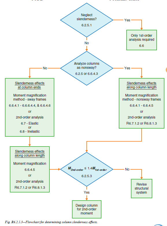
Fig. R6.2.5.3—Flowchart for determining column slenderness effects. | |
| | |
| No further reproduction or distribution is permitted. | |
| | |
| | |
[ Lanjut Ke 6.3—Modeling assumptions ... ] | |
| |
| |
| |