| |
| |
= 5. CHAPTER 5 — LOADS | |
| | |
= 5.3 — Load factors and combinations | |
== 5.3.1 Required strength U shall be at least equal to the | |
| effects of factored loads in Table 5.3.1 , with exceptions and | |
| additions in 5.3.3 through 5.3.13. | |
| | |
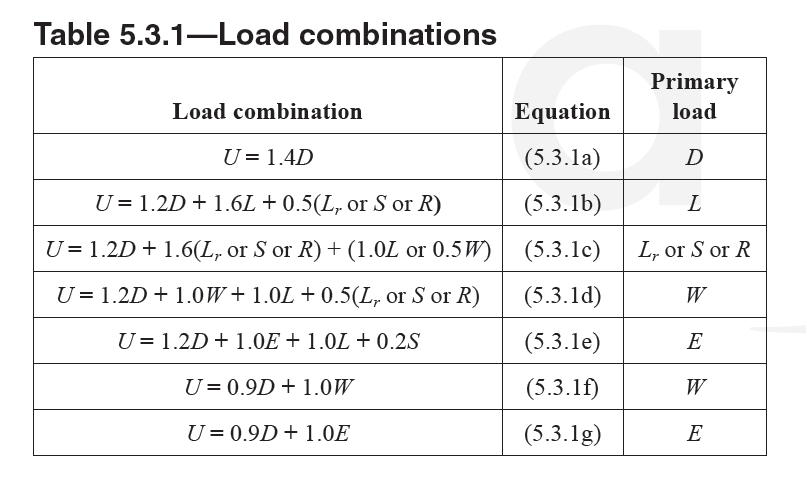
Table 5.3.1—Load combinations | |
| | |
= R5.3 — Load factors and combinations | |
== R5.3.1 The required strength U is expressed in terms of | |
| factored loads. Factored loads are the loads specified in the | |
| general building code multiplied by appropriate load factors. | |
| If the load effects such as internal forces and moments are | |
| linearly related to the loads, the required strength U may be | |
| expressed in terms of load effects multiplied by the appropriate | |
| load factors with the identical result. If the load effects are | |
| nonlinearly related to the loads, such as frame P-delta effects | |
| (Rogowsky and Wight 2010), the loads are factored before | |
| determining the load effects. Typical practice for foundation | |
| design is discussed in R13.2.6.1. Nonlinear finite element | |
| analysis using factored load cases is discussed in R6.9.3. | |
| The factor assigned to each load is influenced by the | |
| degree of accuracy to which the load effect usually can be | |
| calculated and the variation that might be expected in the | |
| load during the lifetime of the structure. Dead loads, because | |
| they are more accurately determined and less variable, are | |
| assigned a lower load factor than live loads. Load factors | |
| also account for variability in the structural analysis used to | |
| calculate moments and shears. | |
| The Code gives load factors for specific combinations of | |
| loads. In assigning factors to combinations of loading, some | |
| consideration is given to the probability of simultaneous | |
| occurrence. While most of the usual combinations of loadings | |
| are included, it should not be assumed that all cases are | |
| covered. | |
| Due regard is to be given to the sign (positive or negative) | |
| in determining U for combinations of loadings, as one | |
| type of loading may produce effects of opposite sense to that | |
| produced by another type. The load combinations with 0.9D | |
| are included for the case where a higher dead load reduces | |
| the effects of other loads. The loading case may also be critical | |
| for tension-controlled column sections. In such a case, | |
| a reduction in compressive axial load or development of | |
| tension with or without an increase in moment may result in | |
| a critical load combination. | |
| | |

Table R5.2.2—Correlation between seismic-related terminology in model codes | |
| | |
| | |
| American Concrete Institute – Copyrighted © Material – www.concrete.org | |
| _62 ACI 318-19: BUILDING CODE REQUIREMENTS FOR STRUCTURAL CONCRETE | |
| No further reproduction or distribution is permitted. | |
| | |
== R5.3.1 Continuation | |
| Consideration should be given to various combinations of | |
| loading to determine the most critical design condition. This | |
| is particularly true when strength is dependent on more than | |
| one load effect, such as strength for combined flexure and | |
| axial load or shear strength in members with axial load. | |
| If unusual circumstances require greater reliance on the | |
| strength of particular members than circumstances encountered | |
| in usual practice, some reduction in the stipulated | |
| strength reduction factors ϕ or increase in the stipulated load | |
| factors may be appropriate for such members. | |
| Rain load R in Eq. (5.3.1b), (5.3.1c), and (5.3.1d) should | |
| account for all likely accumulations of water. Roofs should be | |
| designed with sufficient slope or camber to ensure adequate | |
| drainage accounting for any long-term deflection of the roof | |
| due to the dead loads. If deflection of roof members may | |
| result in ponding of water accompanied by increased deflection | |
| and additional ponding, the design should ensure that | |
| this process is self-limiting. | |
| Model building codes and design load references refer | |
| to earthquake forces at the strength level, and the corresponding | |
| load factor is 1.0 (ASCE/SEI 7; BOCA 1999; SBC | |
| 1999; UBC (ICBO 1997); 2018 IBC). In the absence of a | |
| general building code that prescribes strength level earthquake | |
| effects, a higher load factor on E would be required. | |
| The load effect E in model building codes and design load | |
| reference standards includes the effect of both horizontal and | |
| vertical ground motions (as Eh and Ev, respectively). The | |
| effect for vertical ground motions is applied as an addition | |
| to or subtraction from the dead load effect (D), and it applies | |
| to all structural elements, whether part of the seismic forceresisting | |
| system or not, unless specifically excluded by the | |
| general building code. | |
| | |
| | |
== 5.3.2 The effect of one or more loads not acting simultaneously | |
| shall be investigated. | |
== 5.3.3 The load factor on live load L in Eq. (5.3.1c), | |
| (5.3.1d), and (5.3.1e) shall be permitted to be reduced to 0.5 | |
| except for (a), (b), or (c): | |
| (a) Garages | |
| (b) Areas occupied as places of public assembly | |
| (c) Areas where L is greater than 4.8 kN/m2 | |
== 5.3.4 If applicable, L shall include (a) through (f): | |
| (a) Concentrated live loads | |
| (b) Vehicular loads | |
| (c) Crane loads | |
| (d) Loads on hand rails, guardrails, and vehicular barrier | |
| (e) Impact effects | |
| (f) Vibration effects | |
| | |
| | |
== R5.3.3 The load modification factor in this provision is | |
| different than the live load reductions based on the loaded | |
| area that may be allowed in the general building code. The | |
| live load reduction, based on loaded area, adjusts the nominal | |
| live load (L0 in ASCE/SEI 7) to L. The live load reduction, as | |
| specified in the general building code, can be used in combination | |
| with the 0.5 load factor specified in this provision. | |
| | |
| | |
| | |
| American Concrete Institute – Copyrighted © Material – www.concrete.org | |
| PART 2: LOADS & ANALYSIS 63 | |
| 5 Loads | |
| No further reproduction or distribution is permitted. | |
| | |
== 5.3.5 If wind load W is provided at service-level loads, 1.6W | |
| shall be used in place of 1.0W in Eq. (5.3.1d) and (5.3.1f), and | |
| 0.8W shall be used in place of 0.5W in Eq. (5.3.1c). | |
| | |
== 5.3.6 The structural effects of forces due to restraint of | |
| volume change and differential settlement T shall be considered | |
| in combination with other loads if the effects of T can | |
| adversely affect structural safety or performance. The load | |
| factor for T shall be established considering the uncertainty | |
| associated with the likely magnitude of T, the probability | |
| that the maximum effect of T will occur simultaneously with | |
| other applied loads, and the potential adverse consequences | |
| if the effect of T is greater than assumed. The load factor on | |
| T shall not have a value less than 1.0. | |
| | |
| | |
== R5.3.5 In ASCE/SEI 7-05, wind loads are consistent with | |
| service-level design; a wind load factor of 1.6 is appropriate | |
| for use in Eq. (5.3.1d) and (5.3.1f) and a wind load factor | |
| of 0.8 is appropriate for use in Eq. (5.3.1c). ASCE/SEI 7-16 | |
| prescribes wind loads for strength-level design and the wind | |
| load factor is 1.0. Design wind speeds for strength-level | |
| design are based on storms with mean recurrence intervals | |
| of 300, 700, and 1700 years depending on the risk category | |
| of the structure. The higher load factors in 5.3.5 apply where | |
| service-level wind loads corresponding to a 50-year mean | |
| recurrence interval are used for design. | |
| | |
== R5.3.6 Several strategies can be used to accommodate | |
| movements due to volume change and differential settlement. | |
| Restraint of such movements can cause significant member | |
| forces and moments, such as tension in slabs and shear forces | |
| and moments in vertical members. Forces due to T effects | |
| are not commonly calculated and combined with other load | |
| effects. Rather, designs rely on successful past practices | |
| using compliant structural members and ductile connections | |
| to accommodate differential settlement and volume change | |
| movement while providing the needed resistance to gravity | |
| and lateral loads. Expansion joints and construction closure | |
| strips are used to limit volume change movements based on | |
| the performance of similar structures. Shrinkage and temperature | |
| reinforcement, which may exceed the required flexural | |
| reinforcement, is commonly proportioned based on gross | |
| concrete area rather than calculated force. | |
| Where structural movements can lead to damage of | |
| nonductile elements, calculation of the predicted force | |
| should consider the inherent variability of the expected | |
| movement and structural response. | |
| A long-term study of the volume change behavior of | |
| precast concrete buildings (Klein and Lindenberg 2009) | |
| recommends procedures to account for connection stiffness, | |
| thermal exposure, member softening due to creep, and other | |
| factors that influence T forces. | |
| Fintel et al. (1986) provides information on the magnitudes | |
| of volume change effects in tall structures and recommends | |
| procedures for including the forces resulting from | |
| these effects in design. | |
| | |
| | |
| | |
== 5.3.7 If fluid load F is present, it shall be included in the | |
| load combination equations of 5.3.1 in accordance with (a), | |
| (b), (c), or (d): | |
| (a) If F acts alone or adds to the effects of D, it shall be | |
| included with a load factor of 1.4 in Eq. (5.3.1a). | |
| (b) If F adds to the primary load, it shall be included with | |
| a load factor of 1.2 in Eq. (5.3.1b) through (5.3.1e). | |
| (c) If the effect of F is permanent and counteracts the | |
| primary load, it shall be included with a load factor of 0.9 | |
| in Eq. (5.3.1g). | |
| | |
| | |
| American Concrete Institute – Copyrighted © Material – www.concrete.org | |
| _64 ACI 318-19: BUILDING CODE REQUIREMENTS FOR STRUCTURAL CONCRETE | |
| No further reproduction or distribution is permitted. | |
| | |
== 5.3.7 Continuation | |
| (d) If the effect of F is not permanent but, when present, | |
| counteracts the primary load, F shall not be included in | |
| Eq. (5.3.1a) through (5.3.1g). | |
| | |
== 5.3.8 If lateral earth pressure H is present, it shall be | |
| included in the load combination equations of 5.3.1 in accordance | |
| with (a), (b), or (c): | |
| (a) If H acts alone or adds to the primary load effect, it | |
| shall be included with a load factor of 1.6. | |
| (b) If the effect of H is permanent and counteracts the | |
| primary load effect, it shall be included with a load factor | |
| of 0.9. | |
| (c) If the effect of H is not permanent but, when present, | |
| counteracts the primary load effect, H shall not be | |
| included. | |
| | |
== 5.3.9 If a structure is in a flood zone, the flood loads and | |
| the appropriate load factors and combinations of ASCE/SEI | |
| 7 shall be used. | |
== 5.3.10 If a structure is subjected to forces from atmospheric | |
| ice loads, the ice loads and the appropriate load | |
| factors and combinations of ASCE/SEI 7 shall be used. | |
== 5.3.11 Required strength U shall include internal load | |
| effects due to reactions induced by prestressing with a load | |
| factor of 1.0. | |
== 5.3.12 For post-tensioned anchorage zone design, a load | |
| factor of 1.2 shall be applied to the maximum prestressing | |
| reinforcement jacking force. | |
== 5.3.13 Load factors for the effects of prestressing used | |
| with the strut-and-tie method shall be included in the load | |
| combination equations of 5.3.1 in accordance with (a) or (b): | |
| (a) A load factor of 1.2 shall be applied to the prestressing | |
| effects where the prestressing effects increase the net force | |
| in struts or ties. | |
| (b) A load factor of 0.9 shall be applied to the prestressing | |
| effects where the prestressing effects reduce the net force | |
| in struts or ties. | |
| | |
== R5.3.8 The required load factors for lateral pressures from | |
| soil, water in soil, and other materials, reflect their variability | |
| and the possibility that the materials may be removed. | |
| The commentary of ASCE/SEI 7 includes additional useful | |
| discussion pertaining to load factors for H. | |
== R5.3.9 Areas subject to flooding are defined by flood | |
| hazard maps, usually maintained by local governmental | |
| jurisdictions. | |
== R5.3.10 Ice buildup on a structural member increases the | |
| applied load and the projected area exposed to wind. ASCE/ | |
| SEI 7 provides maps of probable ice thicknesses due to | |
| freezing rain, with concurrent 3-second gust speeds, for a | |
| 50-year return period. | |
== R5.3.11 For statically indeterminate structures, the | |
| internal load effects due to reactions induced by prestressing | |
| forces, sometimes referred to as secondary moments, can be | |
| significant (Bondy 2003; Lin and Thornton 1972; Collins | |
| and Mitchell 1997). | |
== R5.3.12 The load factor of 1.2 applied to the maximum | |
| tendon jacking force results in a design load of about 113 | |
| percent of the specified prestressing reinforcement yield | |
| strength, but not more than 96 percent of the nominal tensile | |
| strength of the prestressing reinforcement. This compares | |
| well with the maximum anchorage capacity, which is at least | |
| 95 percent of the nominal tensile strength of the prestressing | |
| reinforcement. | |
| | |
| | |
| American Concrete Institute – Copyrighted © Material – www.concrete.org | |
| PART 2: LOADS & ANALYSIS 65 | |
| 5 Loads | |
| No further reproduction or distribution is permitted. | |
| _66 ACI 318-19: BUILDING CODE REQUIREMENTS FOR STRUCTURAL CONCRETE | |
| | |
| | |
| American Concrete Institute – Copyrighted © Material – www.concrete.org | |
| No further reproduction or distribution is permitted. | |
| | |
| | |
[ Lanjut Ke CHAPTER 6—STRUCTURAL ANALYSIS ... ] | |
| |
| |
| |