| |
| |
= 4.5 — Structural analysis | |
== 4.5.1 Analytical procedures shall satisfy compatibility of | |
| deformations and equilibrium of forces. | |
== 4.5.2 The methods of analysis given in Chapter 6 shall be | |
| permitted. | |
| | |
= R4.5 — Structural analysis | |
| The role of analysis is to estimate the internal forces | |
| and deformations of the structural system and to establish | |
| compliance with the strength, serviceability, and stability | |
| requirements of the Code. The use of computers in structural | |
| engineering has made it feasible to perform analysis | |
| of complex structures. The Code requires that the analytical | |
| procedure used meets the fundamental principles of equilibrium | |
| and compatibility of deformations, permitting a number | |
| of analytical techniques, including the strut-and-tie method | |
| required for discontinuity regions, as provided in Chapter 6. | |
| | |
| | |
| American Concrete Institute – Copyrighted © Material – www.concrete.org | |
| 54 ACI 318-19: BUILDING CODE REQUIREMENTS FOR STRUCTURAL CONCRETE | |
| No further reproduction or distribution is permitted. | |
| | |
= 4.6 — Strength | |
== 4.6.1 Design strength of a member and its joints and | |
| connections, in terms of moment, shear, torsional, axial, and | |
| bearing strength, shall be taken as the nominal strength Sn | |
| multiplied by the applicable strength reduction factor ϕ. | |
== 4.6.2 Structures and structural members shall have design | |
| strength at all sections, ϕSn, greater than or equal to the | |
| required strength U calculated for the factored loads and | |
| forces in such combinations as required by this Code or the | |
| general building code. | |
| | |
= R4.6 — Strength | |
| The basic requirement for strength design may be | |
| expressed as follows: | |
| |
| _ design strength ≥ required strength | |
| |
| _ ϕSn ≥ U | |
| |
| In the strength design procedure, the level of safety is | |
| provided by a combination of factors applied to the loads and | |
| strength reduction factors ϕ applied to the nominal strengths. | |
| The strength of a member or cross section, calculated | |
| using standard assumptions and strength equations, along | |
| with nominal values of material strengths and dimensions, | |
| is referred to as nominal strength and is generally designated | |
| Sn. Design strength or usable strength of a member or cross | |
| section is the nominal strength reduced by the applicable | |
| strength reduction factor ϕ. The purpose of the strength | |
| reduction factor is to account for the probability of understrength | |
| due to variations of in-place material strengths and | |
| dimensions, the effect of simplifying assumptions in the | |
| design equations, the degree of ductility, potential failure | |
| mode of the member, the required reliability, and significance | |
| of failure and existence of alternative load paths for | |
| the member in the structure. | |
| This Code, or the general building code, prescribes design | |
| load combinations, also known as factored load combinations, | |
| which define the way different types of loads are | |
| multiplied (factored) by individual load factors and then | |
| combined to obtain a factored load U. The individual load | |
| factors and additive combination reflect the variability in | |
| magnitude of the individual loads, the probability of simultaneous | |
| occurrence of various loads, and the assumptions | |
| and approximations made in the structural analysis when | |
| determining required design strengths. | |
| A typical design approach, where linear analysis is applicable, | |
| is to analyze the structure for individual unfactored | |
| load cases, and then combine the individual unfactored load | |
| cases in a factored load combination to determine the design | |
| load effects. Where effects of loads are nonlinear—for | |
| example, in foundation uplift—the factored loads are applied | |
| simultaneously to determine the nonlinear, factored load | |
| effect. The load effects relevant for strength design include | |
| moments, shears, torsions, axial forces, bearing forces, and | |
| punching shear stresses. Sometimes, design displacements | |
| are determined for factored loads. The load effects relevant | |
| for service design include stresses and deflections. | |
| In the course of applying these principles, the licensed | |
| design professional should be aware that providing more | |
| strength than required does not necessarily lead to a safer | |
| structure because doing so may change the potential failure | |
| mode. For example, increasing longitudinal reinforcement | |
| area beyond that required for moment strength as derived | |
| from analysis without increasing transverse reinforcement | |
| could increase the probability of a shear failure occurring | |
| prior to a flexural failure. Excess strength may be undesirable | |
| for structures expected to behave inelastically during | |
| earthquakes. | |
| | |
| American Concrete Institute – Copyrighted © Material – www.concrete.org | |
| PART 1: GENERAL 55 | |
| 4 Struct. Systems | |
| No further reproduction or distribution is permitted. | |
| | |
= 4.7 — Serviceability | |
== 4.7.1 Evaluation of performance at service load conditions | |
| shall consider reactions, moments, shears, torsions, | |
| and axial forces induced by prestressing, creep, shrinkage, | |
| temperature change, axial deformation, restraint of attached | |
| structural members, and foundation settlement. | |
== 4.7.2 For structures, structural members, and their connections, | |
| the requirements of 4.7.1 shall be deemed to be satisfied | |
| if designed in accordance with the provisions of the | |
| applicable member chapters. | |
= R4.7 — Serviceability | |
| Serviceability refers to the ability of the structural system | |
| or structural member to provide appropriate behavior and | |
| functionality under the actions affecting the system. Serviceability | |
| requirements address issues such as deflections and | |
| cracking, among others. Serviceability considerations for | |
| vibrations are discussed in R6.6.3.2.2 and R24.1. | |
| Except as stated in Chapter 24, service-level load combinations | |
| are not defined in this Code, but are discussed in | |
| Appendix C of ASCE/SEI 7-16. Appendixes to ASCE/SEI 7 | |
| are not considered mandatory parts of the standard. | |
| | |
| | |
= 4.8 — Durability | |
== 4.8.1 Concrete mixtures shall be designed in accordance | |
| with the requirements of 19.3.2 and 26.4, considering applicable | |
| environmental exposure to provide required durability. | |
== 4.8.2 Reinforcement shall be protected from corrosion in | |
| accordance with 20.5. | |
= R4.8 — Durability | |
| The environment where the structure will be located will | |
| dictate the exposure category for materials selection, design | |
| details, and construction requirements to minimize potential | |
| for premature deterioration of the structure caused by environmental | |
| effects. Durability of a structure is also impacted | |
| by the level of preventative maintenance, which is not | |
| addressed in the Code. | |
| Chapter 19 provides requirements for protecting concrete | |
| against major environmental causes of deterioration. | |
| | |
| | |
= 4.9 — Sustainability | |
== 4.9.1 The licensed design professional shall be permitted | |
| to specify in the construction documents sustainability | |
| requirements in addition to strength, serviceability, and | |
| durability requirements of this Code. | |
== 4.9.2 The strength, serviceability, and durability requirements | |
| of this Code shall take precedence over sustainability | |
| considerations. | |
= R4.9 — Sustainability | |
| The Code provisions for strength, serviceability, and | |
| durability are minimum requirements to achieve a safe and | |
| durable concrete structure. The Code permits the owner | |
| or the licensed design professional to specify requirements | |
| higher than the minimums mandated in the Code. | |
| Such optional requirements can include higher strengths, | |
| more restrictive deflection limits, enhanced durability, and | |
| sustainability provisions. | |
| | |
| | |
= 4.10 — Structural integrity | |
== 4.10.1 General | |
=== 4.10.1.1 Reinforcement and connections shall be detailed | |
| to tie the structure together effectively and to improve overall | |
| structural integrity. | |
== 4.10.2 Minimum requirements for structural integrity | |
=== 4.10.2.1 Structural members and their connections shall | |
| be in accordance with structural integrity requirements | |
| in Table 4.10.2.1 . | |
| | |
| | |
| | |
= R4.10 — Structural integrity | |
== R4.10.1 General | |
=== R4.10.1.1 It is the intent of the structural integrity requirements | |
| to improve redundancy and ductility through detailing | |
| of reinforcement and connections so that, in the event of | |
| damage to a major supporting element or an abnormal loading, | |
| the resulting damage will be localized and the structure will | |
| have a higher probability of maintaining overall stability. | |
| Integrity requirements for selected structural member | |
| types are included in the corresponding member chapter in | |
| the sections noted. | |
== R4.10.2 Minimum requirements for structural integrity | |
| Structural members and their connections referred to in | |
| this section include only member types that have specific | |
| requirements for structural integrity. Notwithstanding, | |
| detailing requirements for other member types address | |
| structural integrity indirectly. | |
| | |
| American Concrete Institute – Copyrighted © Material – www.concrete.org | |
| 56 ACI 318-19: BUILDING CODE REQUIREMENTS FOR STRUCTURAL CONCRETE | |
| No further reproduction or distribution is permitted. | |
| | |
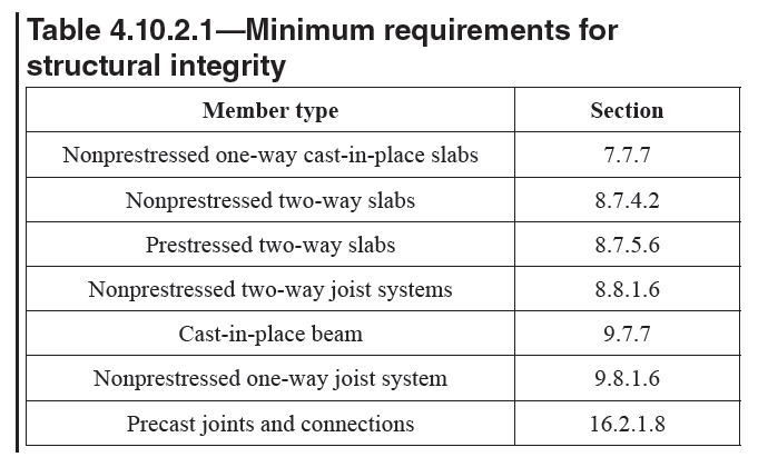
Table 4.10.2.1—Minimum requirements for | |
| _structural integrity | |
| | |
= 4.11 — Fire resistance | |
== 4.11.1 Structural concrete members shall satisfy the fire | |
| protection requirements of the general building code. | |
== 4.11.2 Where the general building code requires a thickness | |
| of concrete cover for fire protection greater than the | |
| concrete cover specified in 20.5.1, such greater thickness | |
| shall govern. | |
= R4.11 — Fire resistance | |
| Additional guidance on fire resistance of structural | |
| concrete is provided by ACI 216.1M. | |
| | |
| | |
= 4.12 — Requirements for specific types of | |
== 4.12.1 Precast concrete systems | |
=== 4.12.1.1 Design of precast concrete members and connections | |
| shall include loading and restraint conditions from | |
| initial fabrication to end use in the structure, including form | |
| removal, storage, transportation, and erection. | |
=== 4.12.1.2 Design, fabrication, and construction of precast | |
| members and their connections shall include the effects of | |
| tolerances. | |
= R4.12 — Requirements for specific types of | |
| This section contains requirements that are related to | |
| specific types of construction. Additional requirements that | |
| are specific to member types appear in the corresponding | |
| member chapters. | |
== R4.12.1 Precast concrete systems | |
| All requirements in the Code apply to precast systems and | |
| members unless specifically excluded. In addition, some | |
| requirements apply specifically to precast concrete. This | |
| section contains specific requirements for precast systems. | |
| Other sections of this Code also provide specific requirements, | |
| such as required concrete cover, for precast systems. | |
| Precast systems differ from monolithic systems in that the | |
| type of restraint at supports, the location of supports, and | |
| the induced stresses in the body of the member vary during | |
| fabrication, storage, transportation, erection, and the final | |
| interconnected configuration. Consequently, the member | |
| design forces to be considered may differ in magnitude and | |
| direction with varying critical sections at various stages of | |
| construction. For example, a precast flexural member may | |
| be simply supported for dead load effects before continuity | |
| at the supporting connections is established and may be a | |
| continuous member for live or environmental load effects | |
| due to the moment continuity created by the connections | |
| after erection. | |
=== R4.12.1.2 For guidance on including the effects of tolerances, | |
| refer to the PCI Design Handbook (PCI MNL 120). | |
| | |
| | |
| American Concrete Institute – Copyrighted © Material – www.concrete.org | |
| PART 1: GENERAL 57 | |
| 4 Struct. Systems | |
| No further reproduction or distribution is permitted. | |
| | |
| | |
=== 4.12.1.3 When precast members are incorporated into a | |
| structural system, the forces and deformations occurring in | |
| and adjacent to connections shall be included in the design. | |
=== 4.12.1.4 Where system behavior requires in-plane loads | |
| to be transferred between the members of a precast floor or | |
| wall system, (a) and (b) shall be satisfied: | |
| (a) In-plane load paths shall be continuous through both | |
| connections and members. | |
| (b) Where tension loads occur, a load path of steel or steel | |
| reinforcement, with or without splices, shall be provided. | |
=== 4.12.1.5 Distribution of forces that act perpendicular | |
| to the plane of precast members shall be established by | |
| analysis or test. | |
=== R4.12.1.5 Concentrated and line loads can be distributed | |
| among members provided the members have sufficient | |
| torsional stiffness and shear can be transferred across | |
| joints. Torsionally stiff members such as hollow-core or | |
| solid slabs will provide better load distribution than torsionally | |
| flexible members such as double tees with thin flanges. | |
| The actual distribution of the load depends on many factors | |
| discussed in detail in LaGue (1971), Johnson and Ghadiali | |
| (1972), Pfeifer and Nelson (1983), Stanton (1987, 1992), | |
| PCI Manual for the Design of Hollow Core Slabs and Walls | |
| (PCI MNL 126), Aswad and Jacques (1992), and the PCI | |
| Design Handbook (PCI MNL 120). Large openings can | |
| cause significant changes in distribution of forces. | |
| | |
| | |
== 4.12.2 Prestressed concrete systems | |
=== 4.12.2.1 Design of prestressed members and systems shall | |
| be based on strength and on behavior at service conditions | |
| at all critical stages during the life of the structure from the | |
| time prestress is first applied. | |
=== 4.12.2.2 Provisions shall be made for effects on adjoining | |
| construction of elastic and plastic deformations, deflections, | |
| changes in length, and rotations due to prestressing. Effects | |
| of temperature change, restraint of attached structural | |
| members, foundation settlement, creep, and shrinkage shall | |
| also be considered. | |
=== 4.12.2.3 Stress concentrations due to prestressing shall be | |
| considered in design. | |
=== 4.12.2.4 Effect of loss of area due to open ducts shall be | |
| considered in computing section properties before grout in | |
| post-tensioning ducts has attained design strength. | |
=== 4.12.2.5 Post-tensioning tendons shall be permitted to | |
| be external to any concrete section of a member. Strength | |
| and serviceability design requirements of this Code shall be | |
| used to evaluate the effects of external tendon forces on the | |
| concrete structure. | |
| | |
== R4.12.2 Prestressed concrete systems | |
| Prestressing, as used in the Code, may apply to pretensioning, | |
| bonded post-tensioning, or unbonded posttensioning. | |
| All requirements in the Code apply to prestressed | |
| systems and members, unless specifically excluded. This | |
| section contains specific requirements for prestressed | |
| concrete systems. Other sections of this Code also provide | |
| specific requirements, such as required concrete cover for | |
| prestressed systems. | |
| Creep and shrinkage effects may be greater in prestressed | |
| than in nonprestressed concrete structures because of the | |
| prestressing forces and because prestressed structures typically | |
| have less bonded reinforcement. Effects of movements | |
| due to creep and shrinkage may require more attention than | |
| is normally required for nonprestressed concrete. These | |
| movements may increase prestress losses. | |
| Design of externally post-tensioned construction should | |
| consider aspects of corrosion protection and fire resistance | |
| that are applicable to this structural system. | |
| | |
| | |
| American Concrete Institute – Copyrighted © Material – www.concrete.org | |
| 58 ACI 318-19: BUILDING CODE REQUIREMENTS FOR STRUCTURAL CONCRETE | |
| No further reproduction or distribution is permitted. | |
| | |
| | |
== R4.12.3 Composite concrete flexural members | |
| This section addresses structural concrete members, either | |
| precast or cast-in-place, prestressed or nonprestressed, | |
| consisting of concrete cast at different times intended to act | |
| as a composite member when loaded after concrete of the | |
| last stage of casting has set. All requirements in the Code | |
| apply to these members unless specifically excluded. In | |
| addition, some requirements apply specifically to composite | |
| concrete flexural members. This section contains requirements | |
| that are specific to these elements and are not covered | |
| in the applicable member chapters. | |
| | |
== 4.12.3 Composite concrete flexural members | |
=== 4.12.3.1 This Code shall apply to composite concrete flexural | |
| members as defined in Chapter 2. | |
=== 4.12.3.2 Individual members shall be designed for all critical | |
| stages of loading. | |
=== 4.12.3.3 Members shall be designed to support all loads | |
| introduced prior to full development of design strength of | |
| composite members. | |
=== 4.12.3.4 Reinforcement shall be detailed to minimize | |
| cracking and to prevent separation of individual components | |
| of composite members. | |
== 4.12.4 Structural plain concrete systems | |
=== 4.12.4.1 The design of structural plain concrete members, | |
| both cast-in-place and precast, shall be in accordance with | |
| Chapter 14. | |
| | |
| | |
= 4.13 — Construction and inspection | |
== 4.13.1 Specifications for construction execution shall be | |
| in accordance with Chapter 26. | |
== 4.13.2 Inspection during construction shall be in accordance | |
| with Chapter 26 and the general building code. | |
= R4.13 — Construction and inspection | |
| Chapter 26 has been organized to collect into one location | |
| the design information, compliance requirements, and | |
| inspection provisions from the Code that should be included | |
| in construction documents There may be other information | |
| that should be included in construction documents that is not | |
| covered in Chapter 26. | |
| | |
| | |
= 4.14 — Strength evaluation of existing structures | |
== 4.14.1 Strength evaluation of existing structures shall be | |
| in accordance with Chapter 27. | |
= R4.14 — Strength evaluation of existing structures | |
| Requirements in Chapter 27 for strength evaluation of | |
| existing structures by physical load test address the evaluation | |
| of structures subjected to gravity loads only. | |
| Chapter 27 also covers strength evaluation of existing structures by | |
| analytical evaluation, which may be used for gravity as well | |
| as other loadings such as earthquake or wind. | |
| | |
| American Concrete Institute – Copyrighted © Material – www.concrete.org | |
| PART 1: GENERAL 59 | |
| 4 Struct. Systems | |
| No further reproduction or distribution is permitted. | |
| 60 ACI 318-19: BUILDING CODE REQUIREMENTS FOR STRUCTURAL CONCRETE | |
| American Concrete Institute – Copyrighted © Material – www.concrete.org | |
| No further reproduction or distribution is permitted. | |
| | |
[ Lanjut Ke CHAPTER 5—LOADS ... ] | |
| |
| |
| |